 |
|||
|
|
|||
|
|
|||
| ||||||||||
|
|
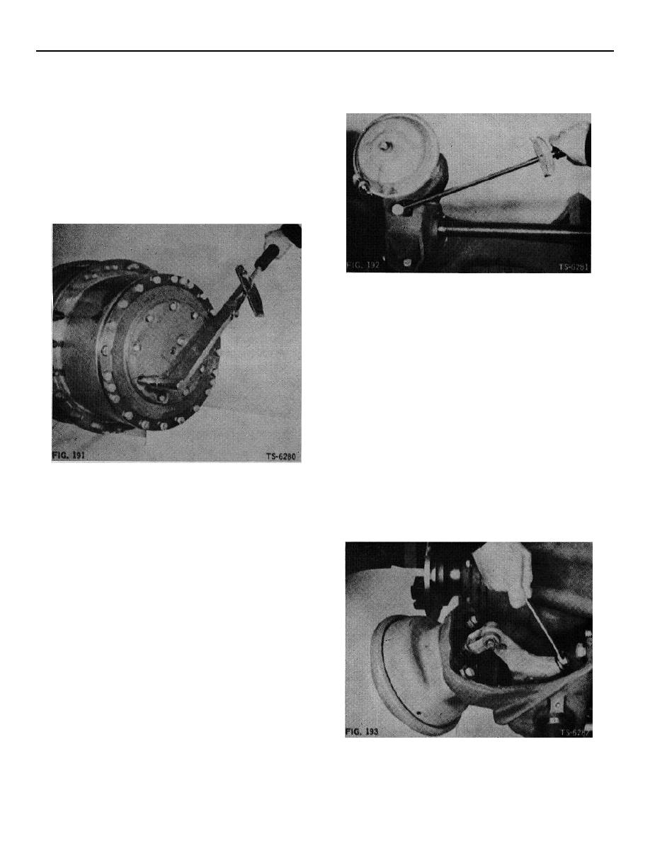
 3. While holding in locking collar, rotate adjusting screw
37. Install cap-to-carrier "O" ring seal in groove in sun
clockwise until 20 ft. lbs. torque is indicated on torque
gear thrust cap assembly. Install thrust cap on
wrench (Fig. 192).
planet carrier. Make certain that "O" ring, if used, is
properly positioned in the groove in the mounting
face, and is not twisted. Apply light coat of
Permatex No. 2 to threads of bolts and install.
Tighten to specified torque (Fig. 191).
NOTE: Early versions of some axles -did not include
"O" ring feature. On these units, apply light coat of
Permatex No. 2 on mounting face of thrust cap be-
fore installing on planet carrier.
4. Back off adjusting screw one-half turn. Locking collar
should automatically return to locking position to lock
adjustment when socket is removed. This provides
proper brake lining-to-drum clearance.
5. After axle is assembled into machine and brake air
lines are connected, recheck broke adjustment as
follows: With minimum air pressure and with brakes
fully activated and applied, adjust at slack adjuster to
obtain 1 1/2 inch travel on brake chamber push rod
when brakes are released. Adjust all slack adjusters on
machine for same travel distance.
Adjust brakes of axle models that have slack adjusters
positioned so that adjusting screw points away from air
chamber bracket as follows:
Brake Adjustment
6. Use 9/16-inch, open-end wrench to make adjustment.
NOTE: Some axle models have slack adjuster posi-
Position wrench on adjusting screw and push in until
tioned so that adjusting screw is adjacent to air cham-
locking collar releases adjusting screw (Fig. 193).
ber bracket (Fig. 192). Others have slack adjuster
positioned so that adjusting screw points away from
air chamber bracket (Fig. 193).
Adjust brakes of axle models that have slack adjusters
positioned so that the adjusting screw is adjacent to the
air chamber bracket as follows:
1. Use torque wrench and 9/16 inch socket to adjust
slack adjusters to attain correct brake lining-to-brake
drum clearance.
2. Position socket on adjusting screw and press it on
screw far enough to cause locking collar to disengage
locking mechanism.
54
|
|
Privacy Statement - Press Release - Copyright Information. - Contact Us |