 |
|||
|
|
|||
|
Page Title:
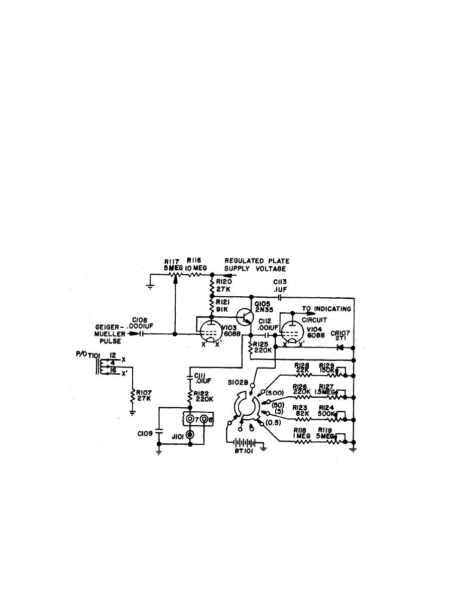
Pulse Shaper and Amplifier Circuit |
|
||
| ||||||||||
|
|
 TM 11-6665-209-40
(5) The negative-going pulses from the detector circuit are now applied through
coupling capacitor C108 to the control grid of tube V103. These pulses drive
the grid of V103 more negative, which cuts off current flow and causes the
plate to become more positive. The rising plate potential of V103 is coupled to
the control grid of V104 by Q105 and C112, which causes V104 to conduct
heavily. Plate voltage for V104 is applied through the component parts of the
indicator circuit. As long as V104 conducts, V103 is cut-off by the rise in the
cathode potential of V104. This rise is caused by the flow of plate current
through common-cathode resistor R107. Capacitor C112 now discharges
through the selected resistance (range) path through switch section S102B to
ground. Tube V104 conducts until discharge of C112 is completed while CR107
eliminates any negative overshoot. At this point the control grid of V104 will
revert to its steady-state bias value and the tube will stop conducting.
1-10
|
|
Privacy Statement - Press Release - Copyright Information. - Contact Us |
