 |
|||
|
|
|||
|
|
|||
| ||||||||||
|
|
 TM 11-6625 -537-14-1
CHAPTER
6
INSTRUCTIONS
GENERAL
SUPPORT
MAINTENANCE
S e c t i o n 1. GENERAL
can ruin a transistor. ( For example, if the
6-1. Scope
bias were shorted out, excessive current
The procedures for troubleshooting and main-
between the base and emitter would ruin
tenance of the electronic voltmeter are contained
the transistor. )
in subsequent sections of this chapter. Where
applicable, the procedures include instructions for
making voltage and resistance measurements and
instructions for replacing components when the
procedure is not obvious.
WARNING
Be extremely careful when servicing the
electronic voltmeter with the case
removed, Voltages in the range of 800
v o l t s are present in the 500-volt dc
reference supply. All metal components
on the dc vtvm printed circuit board will
be at or near the potential indicated by
the voltage readout dials. Always
disconnect the power cord and discharge
the filter capacitors before performing
any servicing procedures.
6.2. Voltage and Resistance Measurements
Use resistor, inductor, and capacitor color codes
c o m p a r e them with readings taken. Normal
voltage and resistance measurements at tube and
transistor sockets are contained in (fig. FO-5). Dc
resistance data for the power transformer are
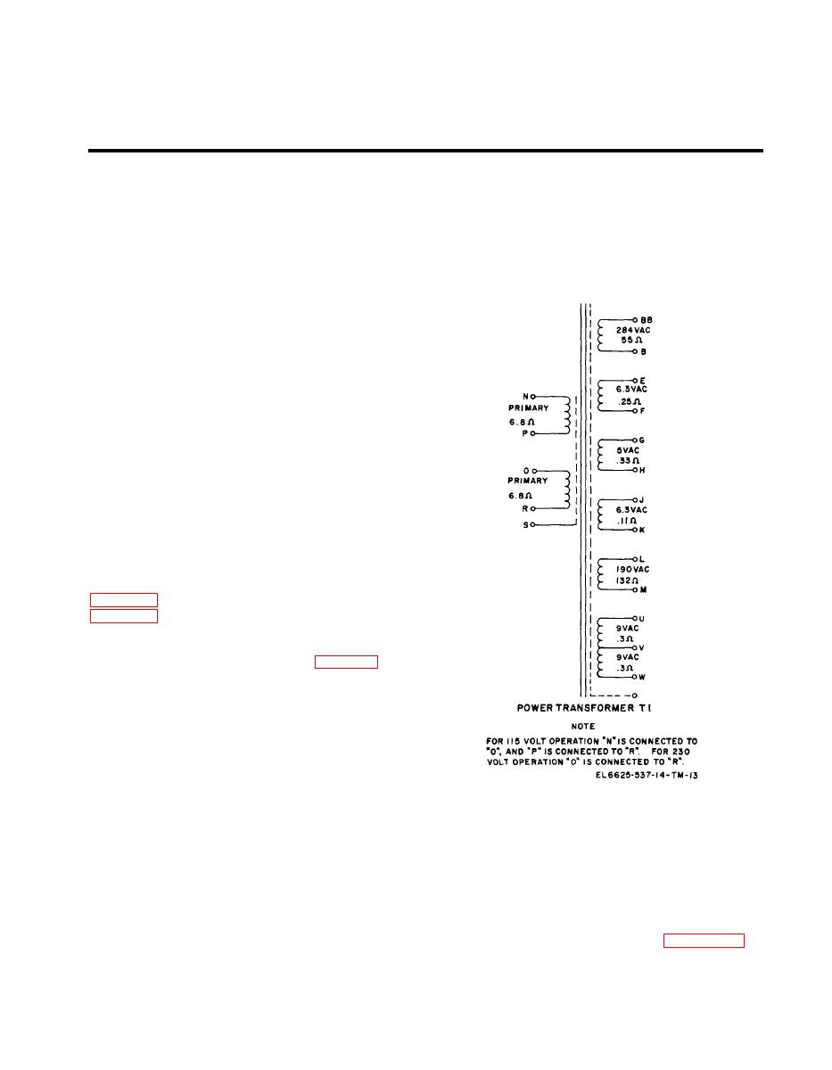
listed in (fig. 6-l).
CAUTION
T h i s equipment contains transistors.
Observe all precautions given to prevent
t r a n s i s t o r damage. Be careful when
making
voltage
and
resistance
measurements. Use tape or sleeving to
Figure 6-1. Power transformer winding dc resistance data.
insulate the entire test prod, except the
extreme tip. A momentary short circuit
Section I l . GENERAL SUPPORT TOOLS AND EQUIPMENT
6-3. Common Tools and T e s t Equipment for
for use by general support maintenance personnel
f o r the electronic voltmeter are listed in the
General Support
Maintenance Allocation Chart in appendix C.
Tools, test equipment, and accessories authorized
6-1
|
|
Privacy Statement - Press Release - Copyright Information. - Contact Us |