 |
|||
|
|
|||
|
Page Title:
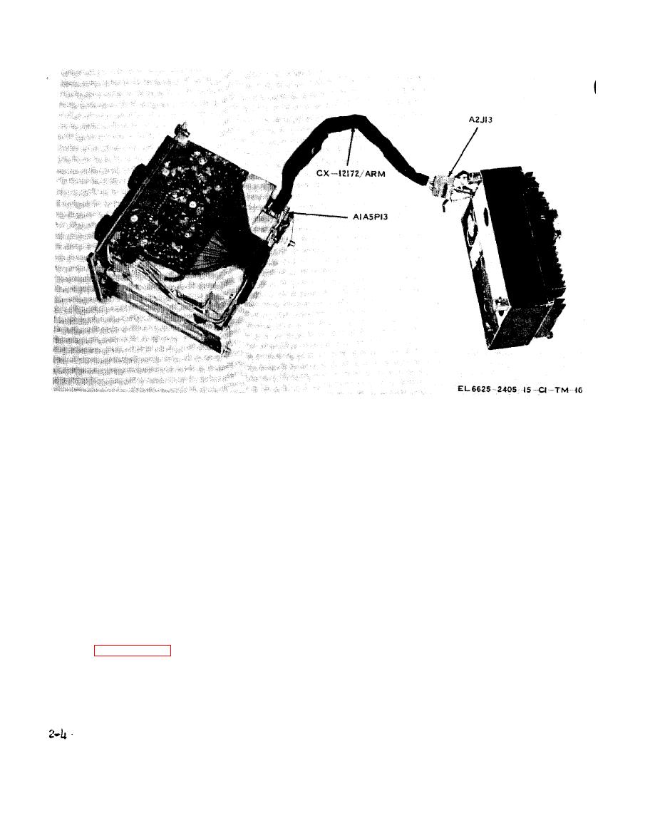
Figure 2-4. Extender cable between AN/ARC-114 sections. |
|
||
| ||||||||||
|
|
 TM 11-6625-2405-15
Figure 2-4. Extender cable between AN/ARC-114 sections.
voltage measurements at any of these points, be
AN/ARC-114, AN/ARC-l15, and AN/ARC-
sure to take into account the position of the func-
116 respectively. (The card extenders are identi-
tion selector switch on the front panel of the ra-
fied by "MP-xxxx" numbers placarded on each ex-
dio set.
tender. ) Insert the removed card into the card ex-
tender. Voltages and resistances car. be checked
Caution
at test points in each connecting line as well as
Connecting pins on the 4-3/4" wide ex-
test points provided on the pluckout cards.
tender boards are easily damaged. Be
c. To measure input current draw, turn off the
careful to avoid bending any of these
power source and set the toggle switch on the
while inserting boards into the radio set
breakout box to OFF. Connect an ammeter (or a
or connecting pluck-out boards into the
multimeter set for current measurements) to
extender cards.
jacks D and D1 of the A2J1 test points. Turn on
the power source, and set the radio set function
out cards are required, remove the card to be
selector switch to any position other than OFF.
checked and insert the proper card extender into
Keep the toggle switch of the breakout box at
the empty socket. The card extender to be used is
OFF; closing that switch will short terminals D
listed in paragraph 1-6b, c, or d for Radio Sets
and D1 and the ammeter will read zero.
Change 1
|
|
Privacy Statement - Press Release - Copyright Information. - Contact Us |