 |
|||
|
|
|||
|
|
|||
| ||||||||||
|
|
 T.O. 12P4-2APX-192
NAVAIR 16-35TS1843-1
TM 11-6625-1646-25
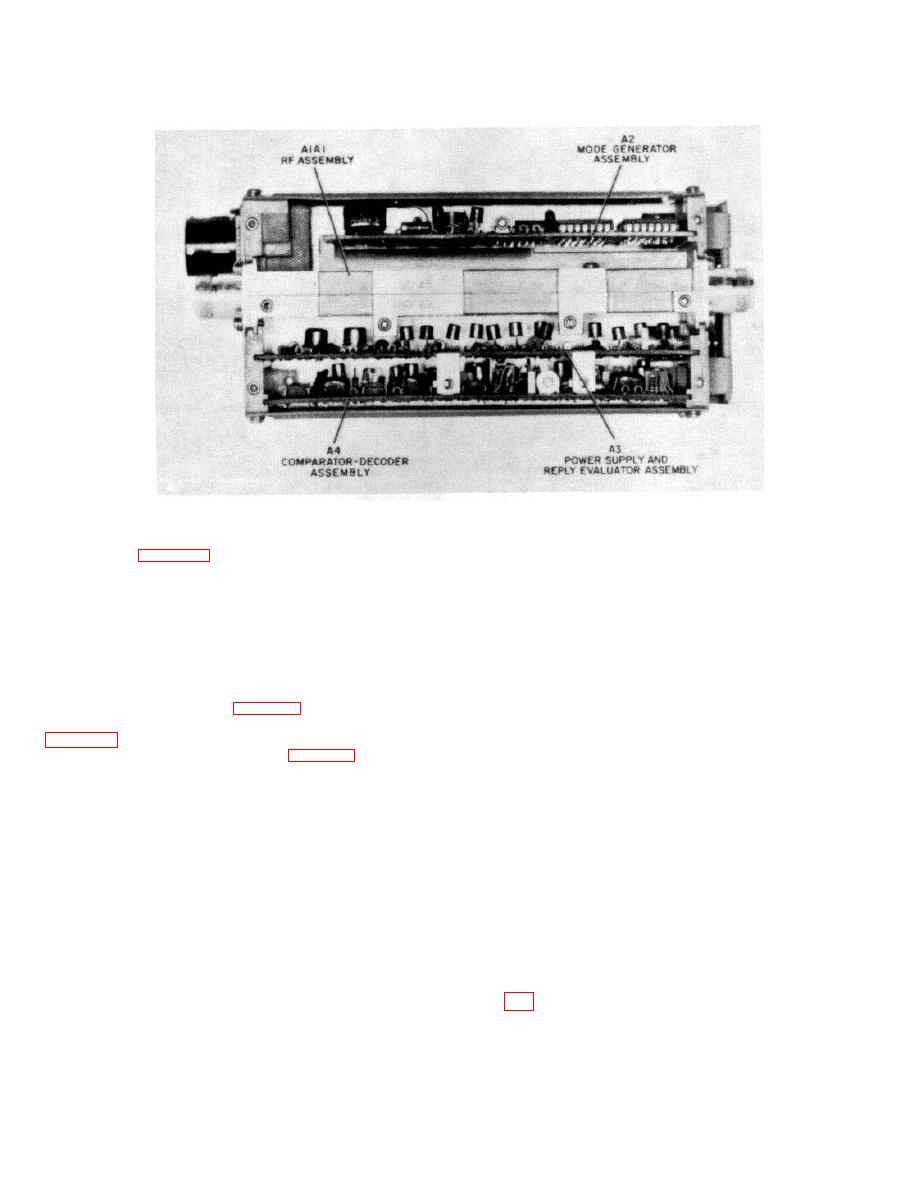
Figure 8-1. Assembly Locations
6 AMP POWER circuit breaker
ON
Each block in figure 8-6 contains specific instructions which,
METER SELECT
DC
when followed, will result in one of the conditions indicated by
DC CONTROL
Adjust for
a line. By following the line indicating the observed condition
28 volts dc.
the technician will be let to a faulty circuit board which should
METER SELECT
AC
be replaced or in some cases to a troubleshooting table. The
AC CONTROL
Adjust for
troubleshooting table will enable the technician to perform a
115 volts ac.
limited amount of maintenance. The chart will also point out
TEST CONDITION
VOLTS
those faulty indications for which repair is restricted to depot
4. To troubleshoot assemblies A2 thru A4 use the extender
maintenance. After the faulty assembly has been repaired or
cards.
replaced, return to the starting point.
To perform the
5. When operating the TS-1843A/APX in the monitor mode,
troubleshooting procedures of figure 8-6. proceed as follows:
position controls on AN/UPM-98A as follows:
1. Prepare the TS-1843A,'APX for troubleshooting (refer to
POWER Switches
ON
CAL-CONTROL panel
2. Connect equipment as Illustrated in figure 7-1. Turn on test
METER SELECT
500 PRF
equipment and allow adequate warm-up time per
XTAL MARK & SYNC panel
manufacturer's instructions. Position controls on C-6280(P),
PRF
Adjust for
APX or C-6280A(P)/APX as follows:
CAL-CONTROL
MASTER
NORM
meter indication
IDENT OUT/MIC
OUT
of 400.
M-1/ON/OUT
ON
SYNC
INT.
M-2/ON/OUT
ON
SIF CODER panel
M-3/A/ON/OUT
ON
CODE A through D
0
M-C/ON/OUT
ON
SUB PULSE SELECT
OFF
MODE 1 CODE
73
FUNCTION
N
MODE 3/A/CODE
7700
LEVEL
HI
RAD TEST/OUT/MON
MON
PULSE WIDTH
.45
3. Place AN APM-239A controls and switches in the
AMPLITUDE
8
following positions:
6. Perform troubleshooting in accordance with fig-
ALTITUDE DIGITIZER
OUT
ure 8-6
POWER MODE
AC, DC
8-2
|
|
Privacy Statement - Press Release - Copyright Information. - Contact Us |