 |
|||
|
|
|||
|
Page Title:
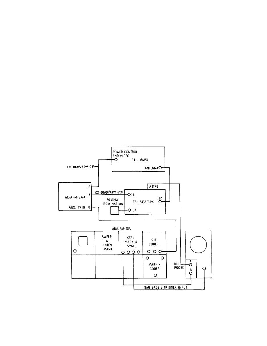
Figure 7-2. Bracket Spacing Alignment Set-up |
|
||
| ||||||||||
|
|
 T.O. 12P4-2APX-192
NAVAIR 16-35TS1843-1
TM 11-6625-1646-25
5. Move C-6280(P)/APX or C-6280A(P)/APX MASTER switch
3. Place AN/APM-239A controls and switches in the
to NORM position. C-6280(P)/APX or C-6280A(P)/APX TEST
following positions:
indicator lights.
POWER MODE
AC/DC
6. On AN/UPM-98A, adjust XTAL MARK & SYNC
6 AMP POWER circuit
ON
panel PRF control to obtain 100 indication on CAL-CONTROL
breaker
panel meter.
C-6280(P)/APX or C-6280A(P)/APX TEST
METER SELECT
DC
indicator cycles on and off.
DC CONTROL
Adjust for 28 volts dc.
7. On AN/UPM-98A, readjust XTAL MARK & SYNC
METER SELECT
AC
panel PRF control to obtain 400 indication on CAL-CONTROL
AC CONTROL
Adjust for 115 volts ac.
panel meter.
TEST CONDITION
VOLTS
8. Disconnect cable from AN/APM-239A AUX TRIG
ALTITUDE DIGITIZER
OUT
IN connector.
4. Place C-6280(P)/APX or C-6280A(P)/APX controls
9. Move C-6280(P)/APX or C-6280A(P)/APX M-l/
and switches in the following positions:
ON/OUT switch to M-1 position. TEST indicator lights.
MASTER
STBY
10. Return C-6280(P)/APX or C-6280A(P)/APX M-l
IDENT/OUT/MIC
OUT
switch to OUT position. TEST indicator goes out.
M-1/ON/OUT
ON
11. Repeat steps 9 and 10 for C-6280(P)/APX or C-
M-2/ON/OUT
ON
6280A(P)/APX M-2/ON/OUT, M-3/A/ON/OUT, and M-
M-3/A/ON/OUT
ON
C/ON/OUT switches.
M-C/ON/OUT
ON
12.
Move AN/UPM-98A POWER switches and
MODE 1
73
AN/APM-239A 6 AMP CIRCUIT BREAKER to OFF positions.
MODE 3/A
7700
Disconnect test connections.
RAD TEST/OUT/MON
MON
Figure 7-2. Bracket Spacing Alignment Set-up
7-2
|
|
Privacy Statement - Press Release - Copyright Information. - Contact Us |