 |
|||
|
|
|||
|
Page Title:
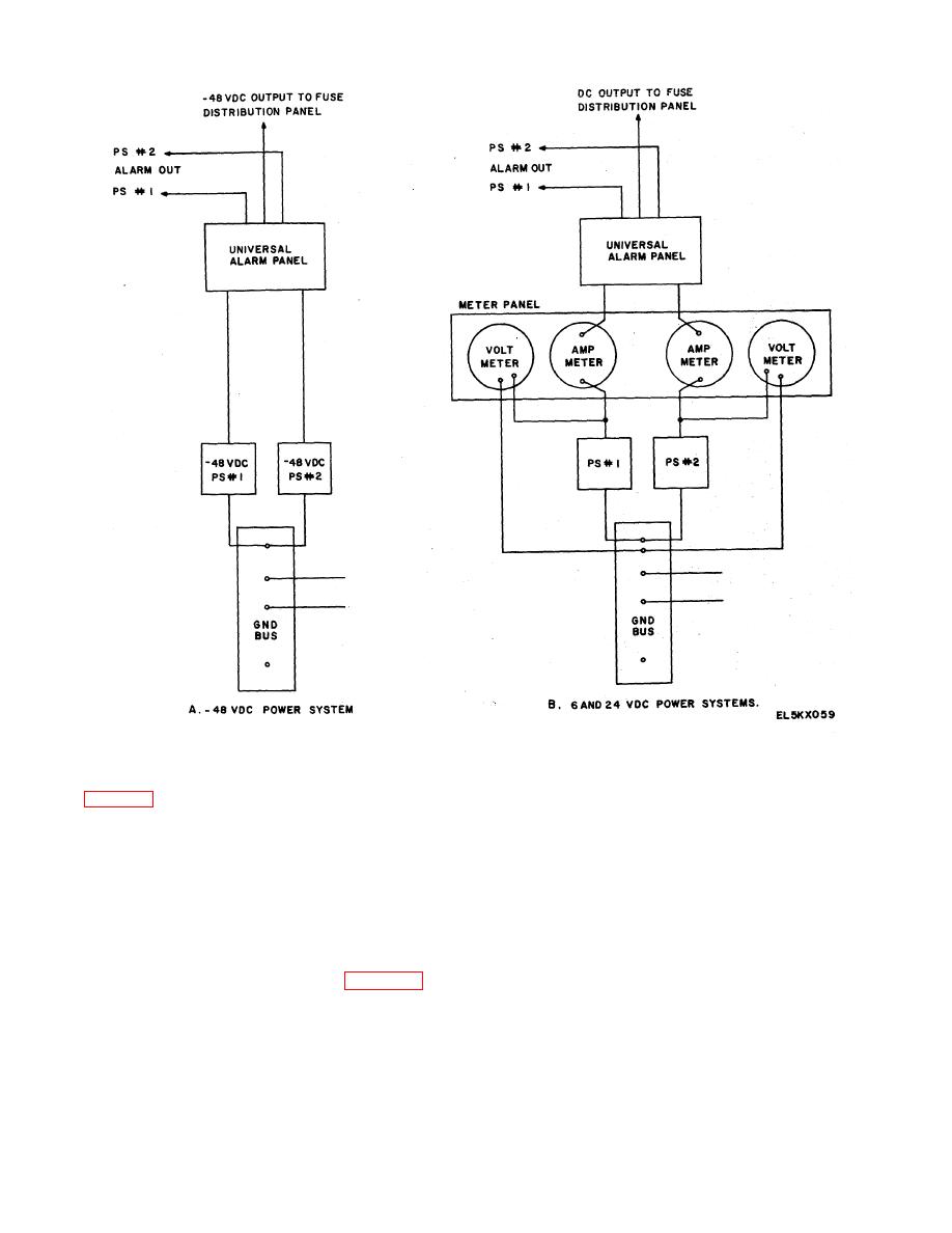
Figure 2-44. Dc Power Systems, Block Diagram |
|
||
| ||||||||||
|
|
 TM 11-5895-878-14&P
Figure 2-44. Dc Power Systems, Block Diagram.
60 causes the outage of two equipments performing the
2-20. Alarm Systems
same function. Minor alarms include equipment alarms
where on-line back-up equipment is available. Red
Two alarm systems (red and black) are provided in the
lights on the alarm panels indicate major alarms while
P&T (a and b below).
amber lights indicate minor alarms. The major/minor
a. Red Alarm System.
The alarm system is
panel is capable of giving a major or minor alarm
designed to alert the technical controller and
indication on a single pushbutton lamp for a single piece
maintenance personnel of equipment degradation
of equipment. The audible alarm (in the audible alarm
and/or failures by giving both an audible and visual
panel) can be silenced by pressing the lighted
alarm. Equipment covered by this alarm system are DC
pushbutton on the major/minor alarm panel.
The
distribution and fuse panels and DC power supplies
various alarm circuits are normally open contacts which
through their associated alarm panel.
The red
provide a ground to the major/minor alarm panel for a
major/minor alarm panel is in bay 2.17 (fig. 1-13). A
fault indication.
major alarm indicates a failure or degradation which 2-
2-60
|
|
Privacy Statement - Press Release - Copyright Information. - Contact Us |
