 |
|||
|
|
|||
|
Page Title:
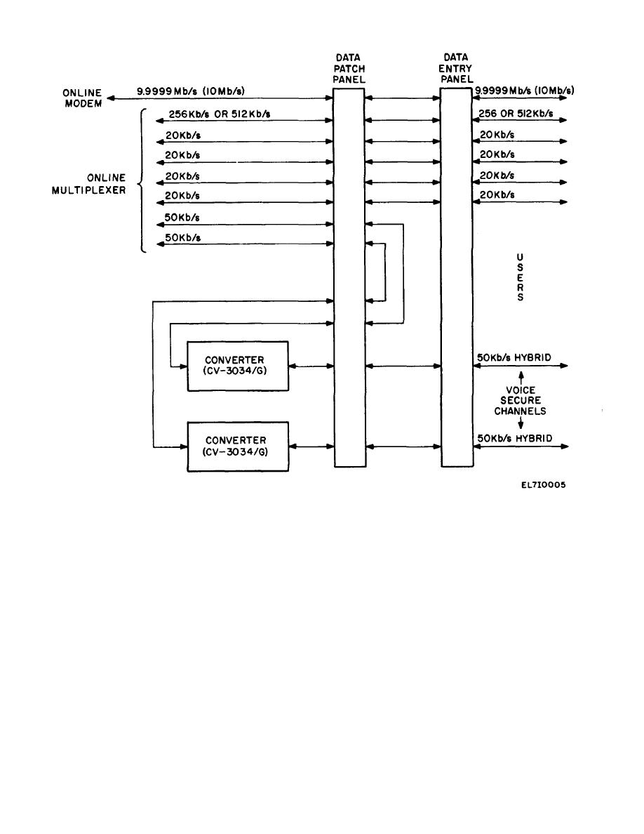
Figure 2-4. Digital Baseband Processing-Simplified Diagram. |
|
||
| ||||||||||
|
|
 TM 11-5895-1123-34
Figure 2-4.
Digital Baseband Processing-Simplified Diagram.
b. The digital inputs from the users can be four 20-
however, can handle data streams of up to a 9.9999
Mb/s rate (commonly referred to as 10 Mb/s). An
kbs/s channels, a 256 or 512-kb/s channel, two 50-kb/s
additional input line is provided at the data entry panel
Hybrid channels, and a channel which can be operated
so that a 10 Mb/s mission bit stream from an external
at any data rate up to 9.9999 Mb/s (10 Mb/ s). The four
multiplexer can be routed directly to the online modem.
20-kb/s channels and the 256/512-kb/s channels are
This input is patched to the modem by way of the data
patched from the data entry panel through the data
patch panel to the multiplexer for further processing.
patch panel.
f. The operation described above is the same for
The two 50-kb/s Hybrid channels, which are externally
receiving data, except the data passes through the unit
encrypted for secure voice transmission, must first pass
in the reverse direction to the field user.
through A-to-D con verters before being sent to the
multiplexer.
c. The A-to-D converters change the analog hybrid
2-6.
Multiplexer/Modem Processing Units
signals applied to the inputs to digital data that is
compatible with the multiplexer input.
a. Figure 2-5 is a simplified diagram of the
d After the analog hybrid signals are converted to digital
Multiplexer/Modem processing functions. As can be
form, they are patched back through the data patch
seen dual equipments are provided throughout this part
panel to the online multiplexer.
of the CSS to provide a backup supplement in case of
e. The multiplexers in the CSS are limited to a
equipment
failure
maximum mission bit stream data rate of 1.544 me 2-8
ing-Simplified Diagram. gabits per second. The modems,
.
2-8
|
|
Privacy Statement - Press Release - Copyright Information. - Contact Us |