 |
|||
|
|
|||
|
Page Title:
DISASSEMBLY AND REASSEMBLY OF CLUTCH AND BRAKE ASSEMBLY - Continued |
|
||
| ||||||||||
|
|
 TM11-3895-209-14
5-11. DISASSEMBLY AND REASSEMBLY OF CLUTCH AND BRAKE ASSEMBLY - Continued
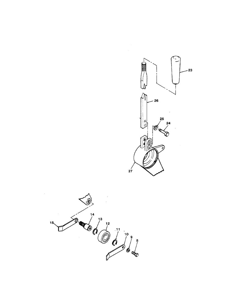
AF Attach the control arm (26) to the idler arm (27) by
means of the two bolts (24) and lock washers (25).
AG Screw the control lever handle (23) onto the control
arm (26).
AH Place the inner drive belt guide (15) on the idler shaft
(14), and screw the idler shaft into the idler arm (27).
When tightened in position, the belt guide should
form a right angle with the centerline of the idler arm.
Install the retaining ring (13), idler bearing (12), and
Al
retaining ring (11) on the idler shaft (14).
AJ Install the outer drive belt guide (10), lock washer (9),
and bolt (8) on the idler shaft (14). Aline the outer
guide parallel to the inner guide and tighten the bolt.
5-20
|
|
Privacy Statement - Press Release - Copyright Information. - Contact Us |