 |
|||
|
|
|||
|
Page Title:
DISASSEMBLY AND REASSEMBLY OF CLUTCH AND BRAKE ASSEMBLY - Continued |
|
||
| ||||||||||
|
|
 TM 11-3895-209-14
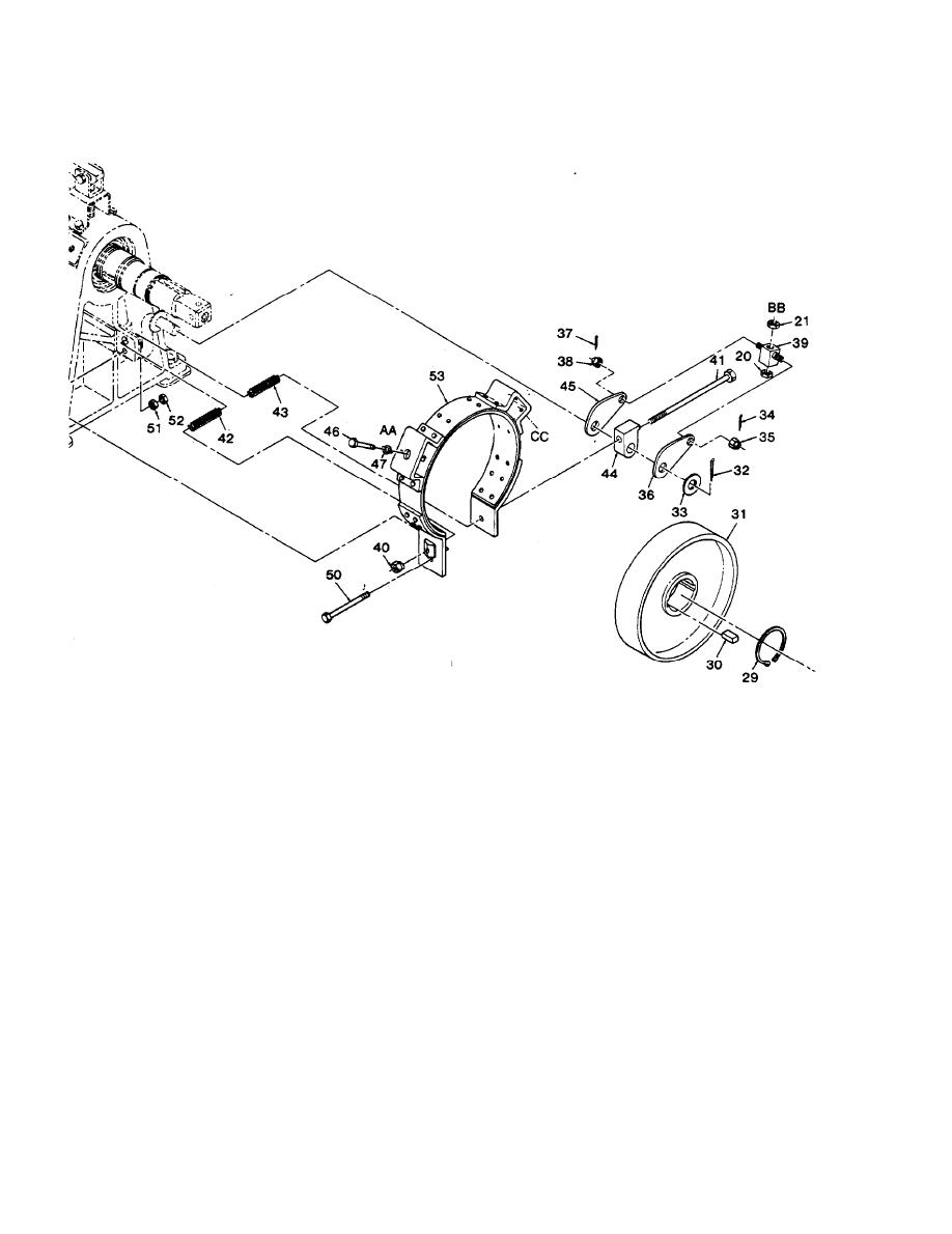
5-11. DISASSEMBLY AND REASSEMBLY OF CLUTCH AND BRAKE ASSEMBLY - Continued
P Insert the bolt (50) through the brake band and the drive bearing housing, and install the two
nuts (51) and (52).
Q Install the brake cam (45) on the lever arm so that the wide side of the brake cam is upward.
R Install the cam stop (44) on the lever arm so that the long end of the stop is up.
S Position the two brake return springs (42) and (43) between the ends of the brake band and the
lug on the housing, and insert the bolt (41) through the cam stop, the brake band, the return
springs, and the housing.
T Install the special brake adjusting nut (40) on the bolt (41).
U Insert one end of the brake cam eye (39) into the hole in the brake cam (45), and install the cas-
tellated hexagonal nut (38) and cotter pin (37).
V Slide the brake cam (36) over the end of the lever arm (59) and the cam eye (39), and install the
washer (33) and cotter pin (37).
W Install the castellated nut (35) and cotter pin (34) on the brake cam eye.
5-18
|
|
Privacy Statement - Press Release - Copyright Information. - Contact Us |