 |
|||
|
|
|||
|
Page Title:
BURNER, FUEL FEEDER TUBE, BOTTOM SHIELD, AND MIXING CHAMBER AND AIR SHUTTER ASSEMBLY. |
|
||
| ||||||||||
|
|
 TM 10-7360-204-13&P
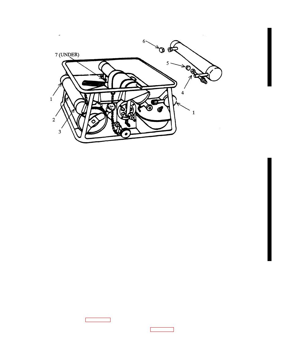
b. Replacement. Replace bad generator with one of the two sparegenerators (1) attached to the unit.
(1) Remove the two screws (2) and (3) that attach the spare generator (1) to the burner unit.
NOTE
Replace screws to secure generator brackets to prevent damage to
bracket during handling of burner unit, and until a new spare
generator is received.
(2) Remove spare generator (1). Remove plastic orifice protective cap (5) and plastic inlet protector plug (6) if not
previously removed.
NOTE
The plastic shipping caps and plugs should be removed from the
spare generator assemblies when they are installed on the Burner
Unit. This will eliminate melting of the plastic caps and plugs during
burner operation.
(3)
Check that fuel orifice nut (4) is installed and tight on generator tube. Insert orifice end of generator into mixing
chamber opening and slide generator to the rear until orifice and mixing chamber mesh.
(4)
Insert generator inlet into fuel feed tube (7) and tighten nut.
4-9.3 BURNER, FUEL FEEDER TUBE, BOTTOM SHIELD, AND MIXING CHAMBER AND AIR SHUTTER
ASSEMBLY.
a. General. The purpose of the burner is to evenly distribute the flame. Fuel vapors pass through the mixing chamber and
out the burner slots and the vapor is ignited. The slots must be clean and free of any foreign matter. The bottom shield helps to
deflect the heat from the fuel tanks.
b. Preliminary Requiremeuts.
Change 11
4-9
|
|
Privacy Statement - Press Release - Copyright Information. - Contact Us |