 |
|||
|
|
|||
|
Page Title:
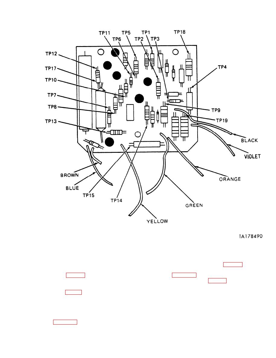
Figure 2-8. Test pointsmodel 03. |
|
||
| ||||||||||
|
|
 TB 9-2920-225-34-1
Figure 2-8. Test pointsmodel 03.
ance checks of the circiut (see figs. 26 and 28
d. Relay.
for test points).
(2) Table 2-2 contains "power on" voltage
terminals (see fig. 2-5). Meter should read ap-
checks of the circuit (see figs. 2-6 and 2-8 for test
proximately 60 ohms.
points).
(2) Place ohmmeter probes across contactor
terminals (see fig. 2-5). Meter should read infinity
f. Functional Check. Check the performance of
(open circuit ).
the regulator on the test stand and make final
(3) If other readings are obtained, replace
voltage adjustments. Voltage output should read
relay with NSN 2920-00-7359542.
28 volts. If the regulator does not function prop-
erly, perform the following:
e. Detailed Circuit Checks.
(1) Check wires and connections.
(1) Table 2-2 contains "power off" resist-
2-9
|
|
Privacy Statement - Press Release - Copyright Information. - Contact Us |