 |
|||
|
|
|||
|
|
|||
| ||||||||||
|
|
 ,
'
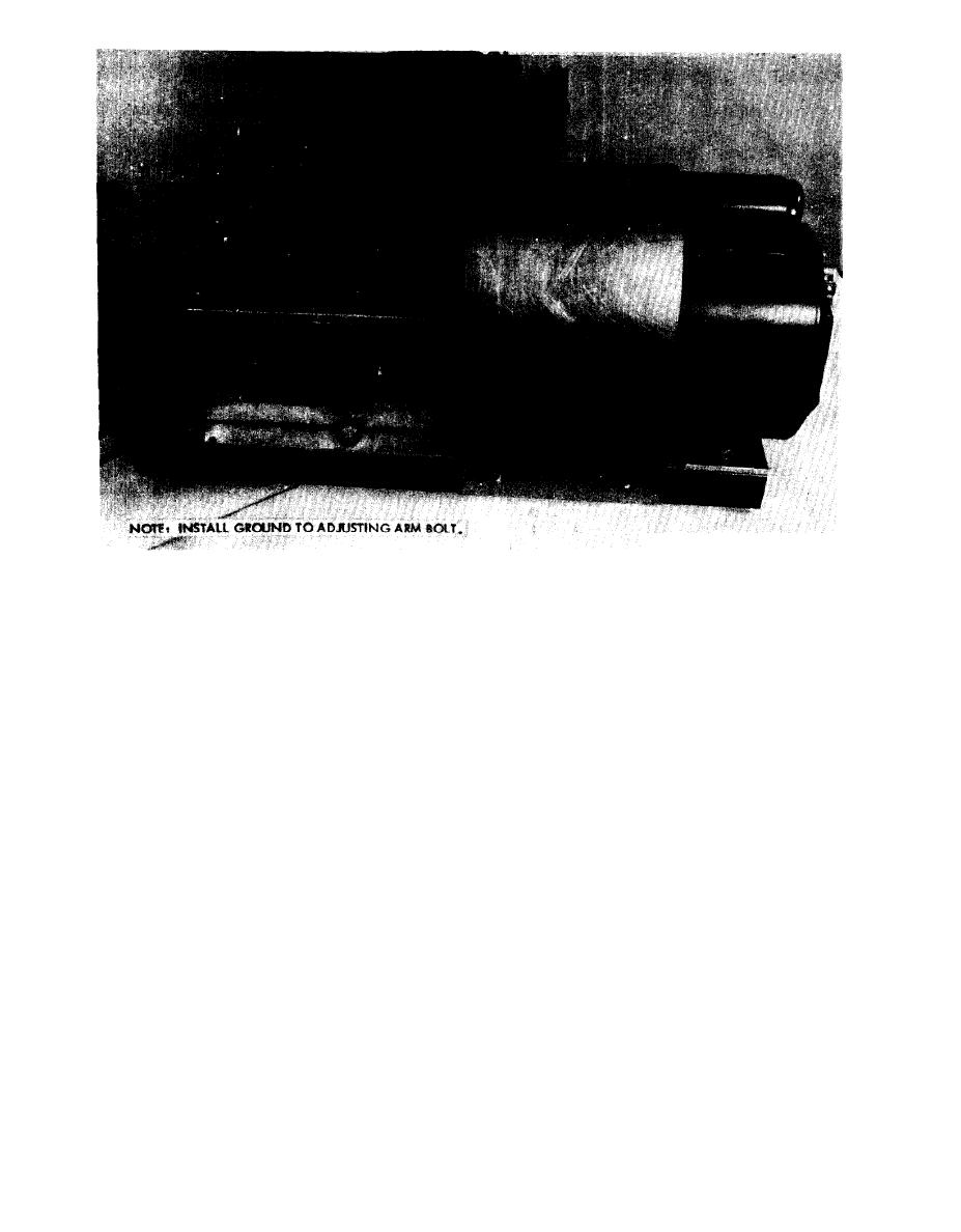
Figure 8. Test setup with generator and regulator.
8. Regulator (Fig. 8). a. Select the pair of con-
e. After insuring that the ON/LOAD SW/OFF
nectors compatible to the regulator to be tested.
switch (fig. 6, item 1) is in the OFF position, set
b. Aline the connectors on the regulator with
the OFF/ON--DRIVE MTR. SW. switch (fig. 6,
item 4) to ON. The voltmeter needle (fig. 6,
those on the tester, keeping the regulator in the
upright position, and push the regulator in to en-
item 5) should be in the green area. If not, replace
the batteries with fully charged batteries.
gage the connectors.
c. Connect the ground strap to the regulator
f. Set the ON/LOAD SW/OFF switch (fig. 6,
item 1) to ON. If any unit is defective, the meter
(25-amp regulator only).
9. Rectifier (fig. 9). a. Aline the connectors with
needle will register in the yellow area, and the
the rectifier in the upside down position and push
part being tested should be replaced.
the rectifier in to engage the connectors.
NOTE
b. Install operable complementary components,
If the motor is overloaded, a circuit
if required. (When checking a generator use a
breaker will turn it off.
To replace a defective item, turn the OFF/ON-
good regulator; etc. )
DRIVE MTR. SW switch to the OFF position,
c. Position the rectifier INT. RECT./100A/
EXT. RECT. position switch (fig. 6, item 3).
and check and replace the defective item (s). Then
proceed as outlined in d above until a complete go
d. Position the generator/alternator 60A/25/
condition exists.
100 selection switch (fig. 6, item 2).
10
|
|
Privacy Statement - Press Release - Copyright Information. - Contact Us |