 |
|||
|
|
|||
|
|
|||
| ||||||||||
|
|
 TM 5-4930-233-14
TM 4930-14/1
AIR COMPRESSOR ASSEMBLY
5-16. CENTRIFUGAL UNLOADER - REPLACE - (Cont.)
a.
Removal- (cont.)
(5)
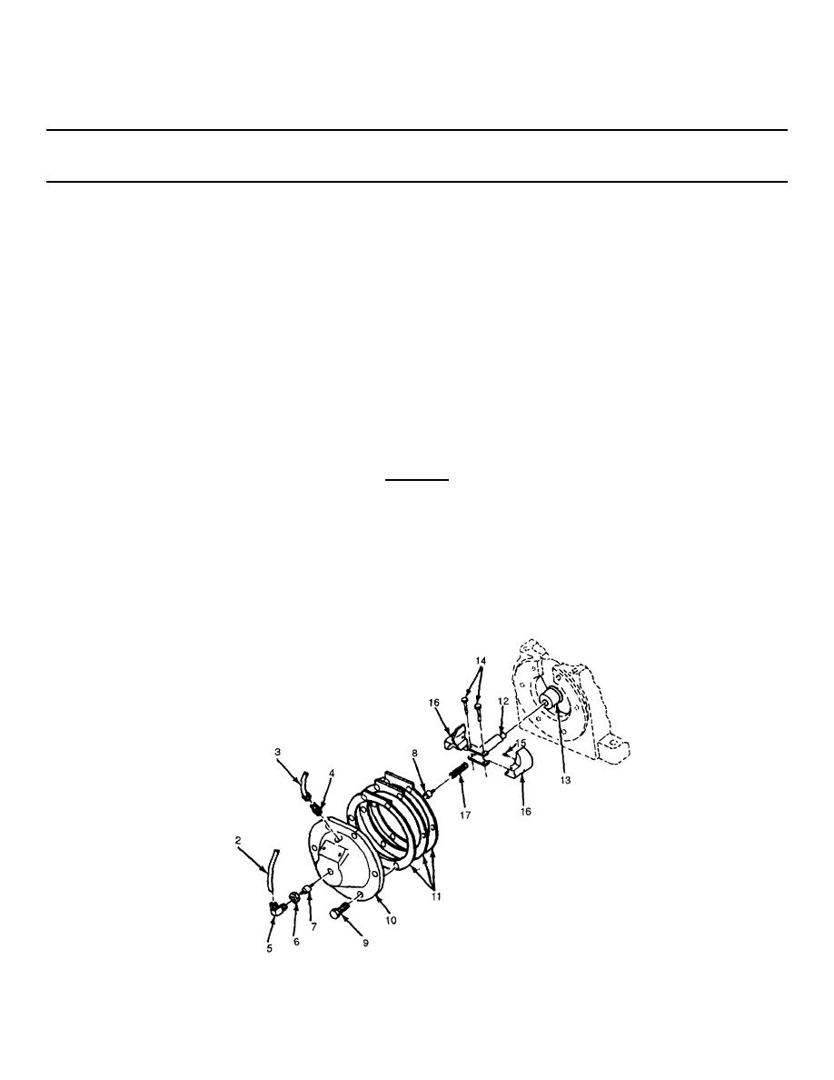
Remove weight retainer and shaft assembly (12) from crankshaft (13).
(6)
Remove two rivets (14), two bumper springs (15), two weights (16) and spring (17).
b.
Installation
(1)
Install spring (17), two weights (16), two bumper springs (15) and two rivets (14).
(2)
Install weight retainer and shaft assembly (12) onto crankshaft (13).
(3)
Install gaskets (11) at same thickness as removed, end cover and cup assembly (10) and six screws (9).
Torque screws to 10 ft lbs (13.56 N-m).
(4)
Insert air valve (8) and plunger (7) into elbow (5) and locknut (6).
CAUTION
Do not screw elbow into end cover too far or malfunction of equipment can occur leading to
permanent equipment damage.
(5)
Screw elbow (5) into end cover until part of valve (8) is visible, when looking into tube opening of elbow.
Tighten locknut (6).
(6)
Install tube connector (4), breather tube assembly (3) and unloading tube (2).
5-86
|
|
Privacy Statement - Press Release - Copyright Information. - Contact Us |
