 |
|||
|
|
|||
|
Page Title:
PRESSURE BLEEDING INSTRUCTIONS: |
|
||
| ||||||||||
|
|
 BRAKE CONTROL:
valve assembly into the end nut and screw the end nut
tightly into the master brake cylinder.
Note: It is very important that the end nut be drawn in
tightly.
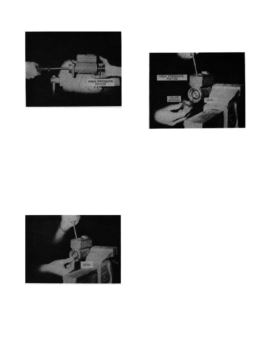
High Pressure Piston Installation
6. While holding the low pressure piston in position,
enter high pressure cup into the low pressure piston. At
this time, force the piston into the cylinder so that the
End Plug Installation
base of the high pressure piston seals on the inside
gasket. This operation will have to be performed under
PRESSURE BLEEDING INSTRUCTIONS:
spring pressure because it is necessary to hold the low
1. Pressure bleeding is performed when master
pressure piston forward in order to ensure proper entry of
brake cylinder is mounted on machine and fully
the cup.
connected. There must be at least 1/32 inch (1 mm) play
7. Release the pressure of the screwdriver or rod
between power cylinder piston and pushrod.
against the pushrod end and at the same time apply
2. Fill reservoir with proper transmission fluid (refer
enough pressure against the base of the high pressure
to LUBRICANTS SPECIFICATION CHART).
piston so as to prevent the high pressure cup from coming
3. Check that all fittings are tight to avoid leakage.
out of the high pressure cylinder.
4. Open bleeder screw on transmission brake,
8. Insert a rod or screwdriver into the relief valve
depress brake pedal and hold'.
opening and pry it sideways against the high pressure
5. Tighten bleeder screw and release pedal. Repeat
piston with enough force to prevent the assembled parts
until all air is removed.
from moving out of position.
6. Recheck
brake
cylinder
fluid
level.
9. While holding the parts in position with the rod or
screwdriver, replace the outside gasket and rubber seal.
Place the retarding
Rev. 760501
K300
70-1.4
|
|
Privacy Statement - Press Release - Copyright Information. - Contact Us |
