 |
|||
|
|
|||
|
Page Title:
Reassembly of Differential and Carrier |
|
||
| ||||||||||
|
|
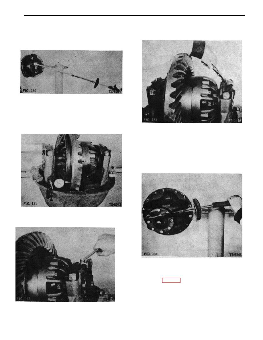 10. Tighten bearing cap bolts to specified torque (Fig.
13. Lockwire together the bearing cap bolts and adjusting
130). With dial indicator, recheck ring gear and
nut bolt (Fig. 133).
pinion backlash. Recheck differential bearings for
end play as described in step 4.
FIG. 130
11. Use dial indicator to check back face of ring gear.
Rotate at least one full turn (Fig. 131). Runout must
not exceed .005 total indicator reading. If runout is
excessive, remove assembly and check for burrs or
dirt under mounting surface of ring gear. Reassemble
FIG. 133
and recheck.
14. Remove companion flange and remove bolts and
washers that were used for temporary installation of
pinion shaft assembly. Coat outside diameter of seal
with Permatex No. 2 and press into pinion oil seal
retainer so' that lip of seal will face toward pinion.
Coat lip with Lubriplate. Install gasket and pinion oil
seal retainer. Secure with 8 bolts and lockwashers
and tighten bolts to specified torque (Fig. 134).
FIG. 131
12. Install adjusting nut lock with bolt and lockwasher
(Fig. 132).
FIG. 134
15. On axle models that do not have a parking brake,
install companion flange on end of pinion shaft with
flat washer and nut. Torque nut to 600 ft. lbs. As
shown in Fig. 120. Secure nut with cotter pin. On
axle models with parking brake, companion flange
should be installed temporarily to facilitate handling
the differential.
42
|
|
Privacy Statement - Press Release - Copyright Information. - Contact Us |
