 |
|||
|
|
|||
|
Page Title:
Reassembly of NoSPIN Differential |
|
||
| ||||||||||
|
|
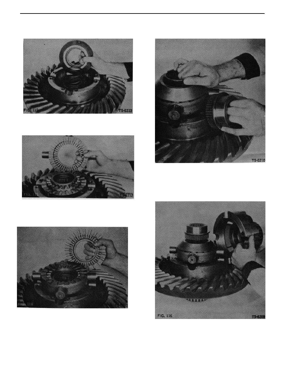 6. Position assembled driven clutch, holdout ring, and
9. Install spring and side gear on driven clutch (Fig.
spring retainer on spring (Fig. 112).
115).
FIG. 112
7. Install assembled spider and center cam on driven
clutch. Make sure that keys on spider engage
keyways on driven clutch (Fig. 113).
FIG. 115
10. Position case half on differential (Fig. 116). Manually
press on case half to compress springs to assure that
case halves seat fully together. If they do not, splines
in the NoSPIN parts are not properly aligned. Align
parts and again check to make sure that case halves
seat fully.
FIG. 113
8. Install the upper driven clutch, with Its assembled
holdout ring and spring retainer, on the spider. Make
sure spider keys engage keyways In driven clutch
(Fig. 114).
FIG. 114
FIG. 116
37
|
|
Privacy Statement - Press Release - Copyright Information. - Contact Us |
