 |
|||
|
|
|||
|
|
|||
| ||||||||||
|
|
 BASIC BLOCK
TESTING AND ADJUSTING
BASIC BLOCK
Main bearings are available with a larger outside diameter
CONNECTING RODS AND PISTONS
than the original size bearings These bearings are for
Use the 5F9059 Piston Ring Expander to remove or
cylinder blocks that have had the bore for the main
install piston rings.
bearings "bored" (made larger than the original size).
Use the IY7426 Piston Ring Compressor or the
4S9450 Compressor and the 4S9446 Clamp from the
FLYWHEEL AND FLYWHEEL HOUSING
4S9458 Teflon Seal Tool Group to install pistons into
cylinder block.
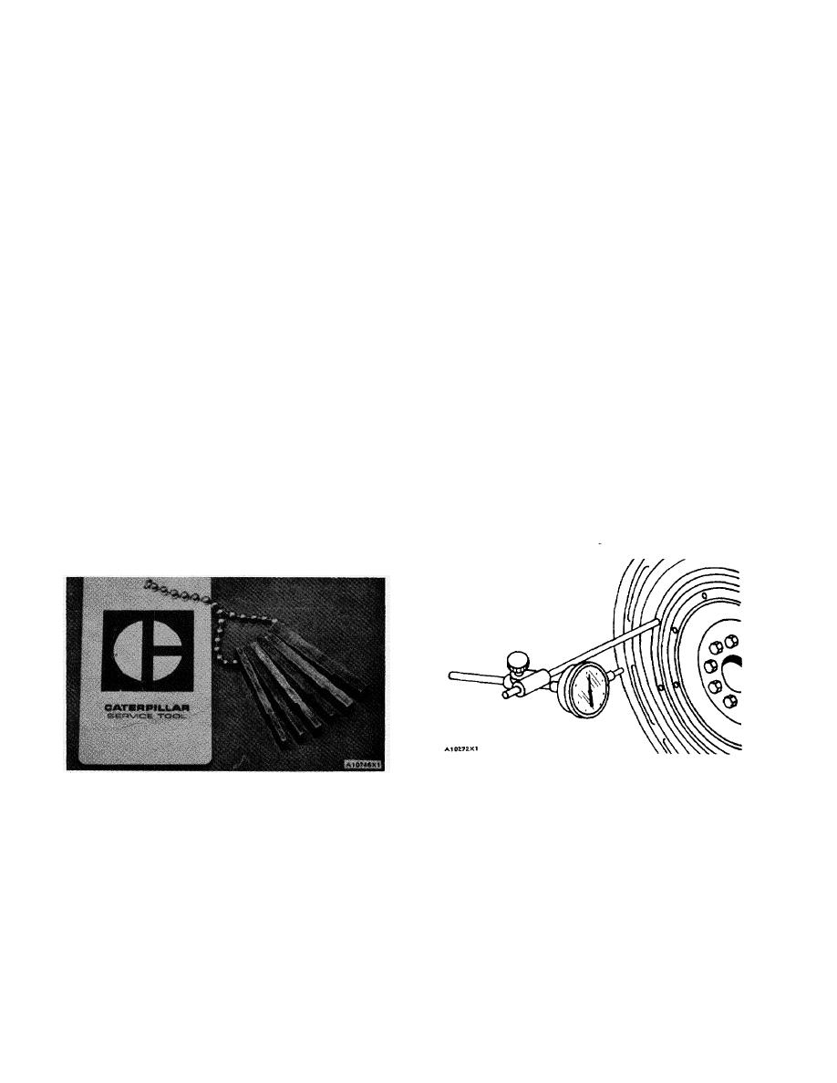
Tools Needed- 8S2328 Dial Indicator Group.
Tighten the connecting rod nuts in the following step
sequence:
Heat the rind gear to install it. Do not heat to more
than 400F (204C). Install the ring gear so the chamfer
1. Put crankcase oil on bolt threads and seating
faces of cap and nut.
on the gear teeth is next to the starter pinion when the
2. Tighten both nuts to 30 3 lb.ft. (4.1 0.4 mkg).
flywheel is installed.
3. Put a mark on each nut and cap.
4. Tighten each nut 60from the mark.
Face Runout (axial eccentricity) of the
Flywheel Housing
The connecting rod bearings should fit tightly in the
bore in the rod. If bearing joints or backs are worn
If any method other than given here is used, always
(fretted), check for bore size as this is an indication of
remember bearing clearances must be removed to get
wear because of looseness.
correct measurements.
5P3519 PISTON RING GROOVE GAUGE
1. Fasten a dial indicator to the crankshaft flange so
the anvil of the indicator will touch the face of the
flywheel housing.
A 5P3519 Piston Ring Groove Gauge is available for
checking ring grooves with straight sides. For instructions
2. Force the crankshaft to the rear before reading
on the use of the gauge, See the GUIDELINE FOR
the indication at each point.
REUSABLE PARTS; PISTONS AND CYLINDER
LINERS, Form No. REG01660.
8S2328 DIAL INDICATOR GROUP INSTALLED
PISTON RING GROOVE GAUGE
3. With dial indicator set at .000 in. (0.0 mm) at location
CONNECTING ROD AND MAIN BEARINGS
(A), turn the crankshaft and read the indicator at locations
(B), (C) and (D).
Bearings are available with a smaller inside diameter
than the original size bearings. These bearings are for
crankshafts that have been "ground" (made smaller than
4. The difference between lower and higher
the original size).
measurements taken at all four points must not be more
than .012 in. (0.30 mm), which is the maximum
permissible face runout (axial eccentricity) of the flywheel
housing.
78
|
|
Privacy Statement - Press Release - Copyright Information. - Contact Us |
