 |
|||
|
|
|||
|
Page Title:
RESTRICTION OF AIR INLET AND EXHAUST |
|
||
| ||||||||||
|
|
 CYLINDER HEAD AND VALVES
TESTING AND ADJUSTING
CYLINDER HEAD AND VALVES
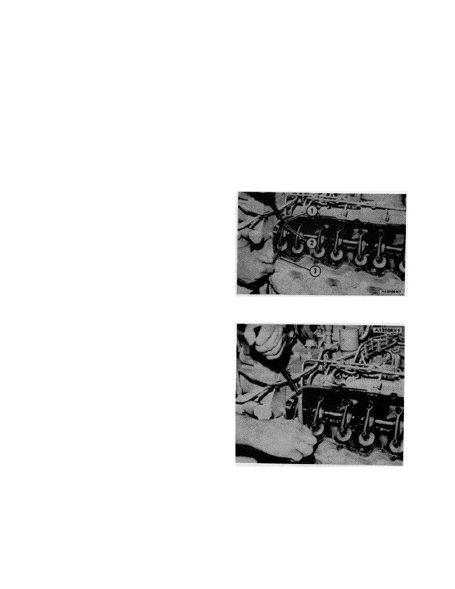
3. Make adjustment to the valves for No.1 and No.2
RESTRICTION OF AIR INLET AND EXHAUST
cylinders. To make the adjustment, loosen
locknut (2). Turn the adjustment screw (1) until
There will be a reduction of horsepower and efficiency
the feeler gauge (3) will go between the end of
of the engine if there is a restriction in the air inlet or
the valve stem and the rocker arm.
exhaust system.
NOTE: Use a . 015 in. (0.38 mm) feeler gauge for the
Air flow through the air cleaner must not have a
intake valves. Use a .025 in. (0.64 mm) feeler gauge for
restriction of more than 25 in. (635 mm) of water
the exhaust valves.
difference in pressure.
4. After the adjustment is complete, hold adjustment
Back pressure from the exhaust (pressure difference
screw (1) and tighten locknut (2) to 24 5 lb. ft.
measurement between exhaust outlet elbow and
(3.3 0.7 mkg). After the locknut is tightened,
atmosphere) must not be more than 34 in. (864 mm) of
check the adjustment again.
water.
COMPRESSION
An engine that runs rough can have a leak at the
valves, or valves that need adjustment. Run the engine at
the speed that gives rough running. To find a cylinder that
has low compression or does not have good fuel ignition,
loosen a fuel line nut at a fuel injection pump. This will
stop the flow of fuel to that cylinder. Do this for each
cylinder until a loosened fuel line is found that makes no
difference in engine rough running. Be sure to tighten
each fuel line nut after the test before the next fuel line
nut is loosened. This test can also be an indication that
the fuel injection is wrong, so more checking of the
VALVE LASH ADJUSTMENT
cylinder will be needed. This test is just a fast method of
1. Adjustment screw. 2. Locknut. 3. Feeler gauge.
finding the cause of compression loss in a cylinder.
Removal of the head and inspection of the valves and
valve seats is necessary to find those small defects that
do not normally cause a problem. Repair of these prob-
lems is normally done when reconditioning (overhaul) the
engine.
CHECKING ADJUSTMENT OF THE
VALVE LASH
Check the adjustment of the valve lash during the first
80 hours of operation and every 500 hours of operation
after the first adjustment. If the engine is not used for 500
hours in six months, check the adjustment of the valve
lash after every six months.
To check and make adjustment to the valve lash, use
the following procedure:
TIGHTENING LOCKNUT
1. Remove the valve covers.
5. Turn he crankshaft 180 CLOCKWISE (as seen
from. front of engine ). The VS mark on the
2. Turn the crankshaft CLOCKWISE (as seen from
damper assembly will be in alignment with the
front of engine) until No.1 piston is at top center
tighting pointer. Make adjustment to the valves
on the compression stroke. The TDC-1 mark on
for No.3 and N.7 cylinders.
the damper assembly will be in alignment with the
timing pointer.
70
|
|
Privacy Statement - Press Release - Copyright Information. - Contact Us |
