 |
|||
|
|
|||
|
Page Title:
GOVERNOR ADJUSTMENTS |
|
||
| ||||||||||
|
|
 FUEL SYSTEM
TESTING AND ADJUSTMENT
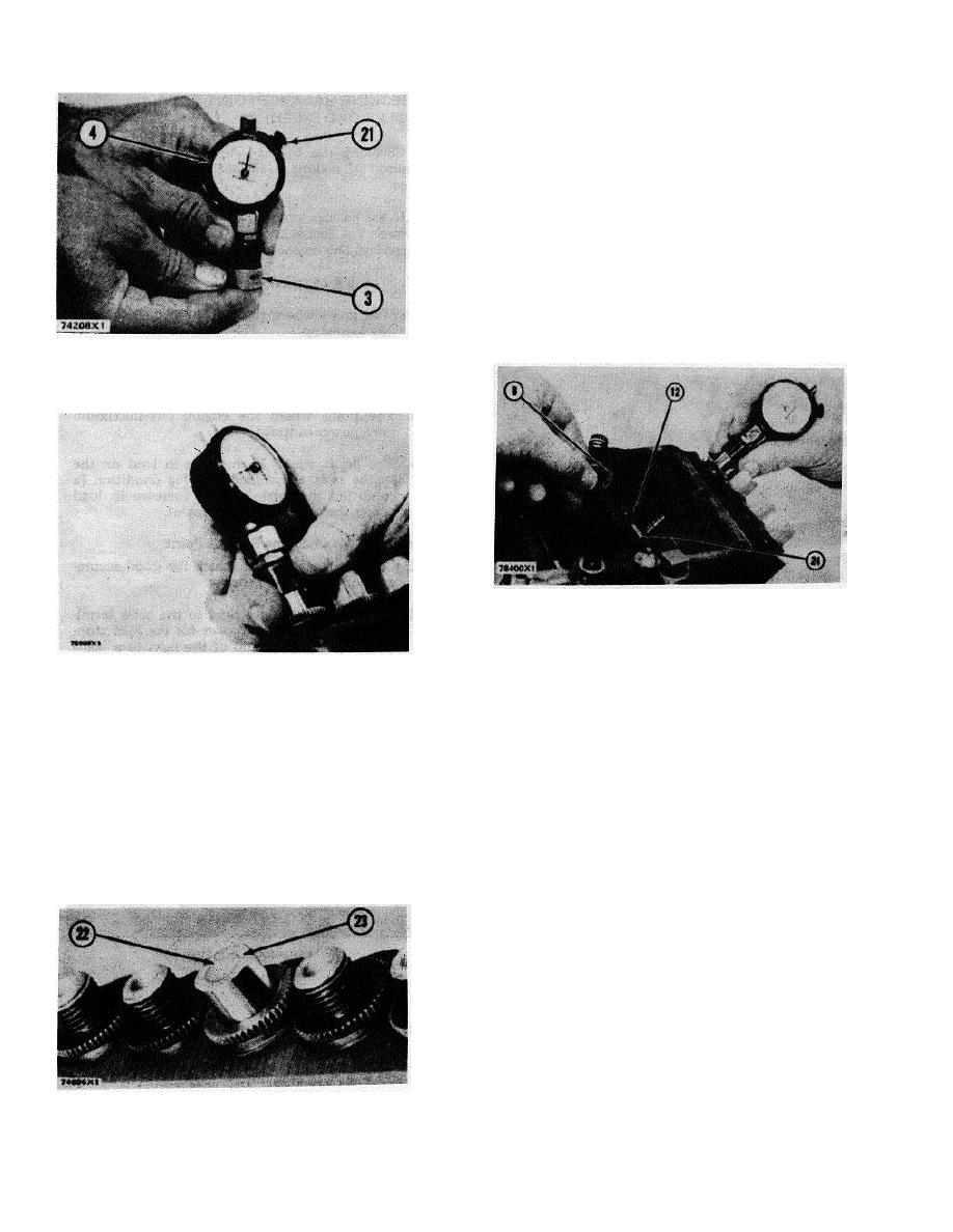
b. With wrench (8) in the screw for lever (12) and
dial indicator held tightly on top of the calibration
pump, use wrench (8) to move lever (12) up or
down until the dimension on the dial indicator is
zero. Tighten the screw to 24 2 lb. in. (27.7
2.3 cm. kg).
c.
After the screw is tightened, use the dial indicator
to check the adjustment again.
13. The calibration of each pump can be checked using
this same procedure. The 1P7379 Microgage is used
to put the dial indicator on zero before the calibration
dimension of each pump is checked.
PUTTING DIAL INDICATOR ON ZERO
3. 1P7379 Microgage. 4. 3P1568 Indicator with 3P2226
Base. 21. Lockscrew.
CALIBRATION OF AN INJECTION PUMP
8. 1S9836 Wrench. 12. Lever. 24. Sleeve control shaft.
CHECKING PUMP CALIBRATION
14. If a pump is checked and an adjustment is made,
again check the dimension after the lever screw is
12. If a pump needs to be calibrated, use the following
tightened.
procedure:
a. Use wrench (8) to loosen the screw that holds
GOVERNOR ADJUSTMENTS
lever (12) on shaft (24). Loosen the screw just
enough so lever (12) can be moved (up or down)
CAUTION: A mechanic that has the correct training is the
on shaft (24).
only one to make the adjustment of low idle and high idle
rpm. The correct low idle and high idle rpm, and the
NOTE: Move the lever and put plunger (22) of the
measurements for adjustment of fuel setting are given in
calibration pump almost flush with top surface (23) of the
the RACK SETTING INFORMATION.
calibration pump.
Check engine rpm with a tachometer that has good
accuracy. If the low idle or high idle rpm needs an
adjustment, use the following procedure:
1. For adjustment of low idle, loosen locknut (2) and turn
adjustment bolt (1) to get as near as possible to the
correct low idle rpm.
2. After the low idle adjustment is correct, tighten
locknut (2).
POSITION OF PLUNGER
22. Plunger. 23. Top surface of calibration pump.
63
|
|
Privacy Statement - Press Release - Copyright Information. - Contact Us |
