 |
|||
|
|
|||
|
|
|||
| ||||||||||
|
|
 FUEL SYSTEM
TESTING AND ADJUSTMENT
NOTE: Some fuel can be at the tip of the fuel injection
nozzle but a rapid flow of drops (dribble) must not be seen.
3. Turn the lift adjustment screw (10) counterclockwise 3/4
1/8 of a turn.
4. Hold the lift adjustment screw (10) with a 5/64" hex
wrench and tighten locknut (9) just enough so that the
lift adjustment screw (10) will not turn.
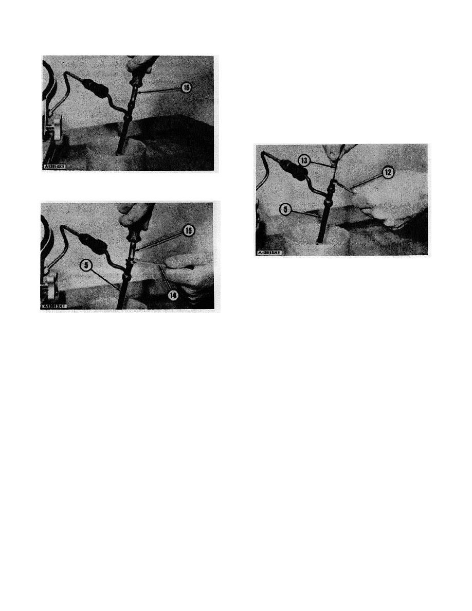
OPENING PRESSURE ADJUSTMENT
15. Spanner-type screwdriver.
TIGHTENING LOCKNUT
5. Fuel injection nozzle. 12. 8H8502 Combination
Wrench. 13. 5/64" Hex Wrench.
Checking Seat Condition
1. Put a shop towel around the top of the body of the fuel
TIGHTENING LOCKNUT
injection nozzle (pressure screw end) to take in the
5. Fuel injection nozzle. 14. 8H8505 Combination
leakage. Close the gauge protector valve.
Wrench. 15. Spanner-type screwdriver.
2. Point the tip of the fuel injection nozzle into the 8S2270
4. After the opening pressure adjustment is made, install
Fuel Collector and operate the pump rapidly for a
the locknut (9) that holds lift adjustment screw (10).
minimum of five strokes to put the valve on the seat.
Make the valve lift adjustment. See VALVE LIFT
Open the gauge protector valve. Be sure the nozzle tip
ADJUSTMENT.
is completely dry.
3. Make the pressure 250 to 300 psi (17.6 to 21.1 kg/cm )
Valve Lift Adjustment
less than the opening pressure. If more than 3 drops of
fuel get on the tip of the fuel injection nozzle in 15
1. With the opening pressure correct arid while pumping
seconds, clean or make replacement to the fuel
test oil through the fuel injection nozzle, hold the locknut
injection nozzle.
(9) and slowly turn the lift adjustment screw (10)
clockwise until the pressure starts to increase above the
Spray Characteristic (Pattern)
opening pressure.
NOTE: The adjustment for the valve lift must be correct
2. Check to be sure the valve is on the seat by making the
before checking the spray pattern.
pressure 200 to 500 psi (14.06 to 35.15 kg/cm2) more
than the opening pressure.
1. Close the gauge protector valve and the on-off valve.
Open the pump isolator valve.
CAUTION: Do not bend the valve or damage the seat by
turning the lift adjustment screw (10) with too much force.
2. Point the tip of the fuel injection nozzle into the 8S2270
Fuel Collector.
47
|
|
Privacy Statement - Press Release - Copyright Information. - Contact Us |
