 |
|||
|
|
|||
|
|
|||
| ||||||||||
|
|
 ELECTRICAL SYSTEM
SYSTEMS OPERATION
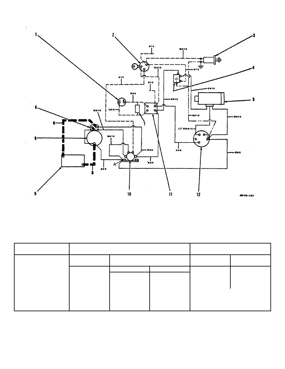
STARTING AND CHARGING SYSTEM
1. Ammeter. 2. Key switch. 3. Fuel shut-off solenoid. 4. Relay. 5. Alternator regulator . 6. Starter solenoid.
7. Shunt. 8. Starting motor. 9. Battery. 10. Solenoid switch. 11. Terminal strip. 12. Alternator.
NOTE: All wires shown as dash lines (----) are to be put on by the customer. All wires shown as phantom lines (-
-----) are for 24V systems only.
MAXIMUM RECOMMENDED
COLOR CODE
TOTAL BATTERY CABLE LENGTH
WIRES MARKED #X
B-Black
CABLE
DIRECT ELECTRIC
CHARGING
WIRE
W-White
SIZE
STARTING
UNIT OUTPUT
SIZE
R-Red
0-18 amps.
#14
12 VOLT
24-32 VOLT
O-Orange
0
4.0 FEET
15.0 FEET
19.30 amps.
#10
BR-Brown
00
5.0 FEET
18.0 FEET
31-45 amps
#8
LT GN-Light Green
000
6.0 FEET
21.0 FEET
46-65 amps.
#6
PU-PurpIe
0000
7.5 FEET
27.0 FEET
NUMBER FOLLOWING COLOR
W/B-White with Black
DESIGNATION INDICATES
Stripe
RECOMMENDED WIRE SIZE
X3560
30
|
|
Privacy Statement - Press Release - Copyright Information. - Contact Us |
