 |
|||
|
|
|||
|
|
|||
| ||||||||||
|
|
 ELECTRICAL SYSTEM
SYSTEMS OPERATION
ELECTRICAL SYSTEM
The electrical system has three separate circuits: the
current (AC) is made; and stationary rectifying diodes that
charging circuit the starting circuit and the low amperage
change alternating current (AC) to direct current (DC).
circuit. Some of the electrical system components are
used in more than one circuit. The battery (batteries)
The alternator field current goes through the brushes.
circuit breaker ammeter cables and wires from the
The field current is 2 to 3 amperes. The rectifying diodes
battery are all common in each of the circuits.
will send current from the alternator to the battery or load
but will not send current from the battery to the alternator.
The charging circuit is in operation when the engine
is running.
An alternator makes electricity for the
Regulator (Motorola)
charging circuit. A voltage regulator in the circuit controls
the electrical output to keep the battery at full charge.
The voltage regulator is a transistorized electronic switch.
It feels the voltage in the system at the switch for oil
The starting circuit is in operation only when the start
pressure and gives the necessary field current to keep the
switch is activated.
needed system voltage. The voltage regulator has two
basic circuits the load circuit and the control circuit.
The low amperage circuit and the charging circuit
are both connected to the same side of the ammeter.
The load circuit has a positive potential from the input
The starting circuit connects to the opposite side of the
lead-of the regulator to the rotor (field) winding. The
control circuit makes the load circuit go off and on at a
rate that will give the needed charging voltage.
SYSTEM COMPONENTS
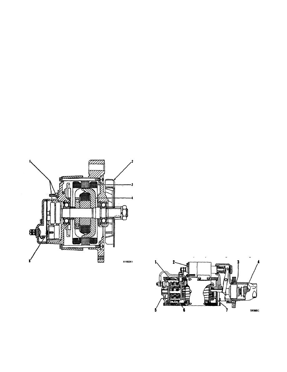
Alternator (Motorola)
Alternator (Delco-Remy)
The alternator is a three phase self rectifying
charging unit. The regulator for the alternator is part of
the alternator.
The alternator is driven from the
crankshaft pulley by two V type belts.
The only part in the alternator which has movement
is the rotor. The rotor is held in position by a ball bearing
at the drive end and a roller bearing at the rectifier end.
The compartment for the regulator is sealed. The
regulator controls the alternator output ac- cording to the
needs of the battery and the other components in the
electrical system.
Starting Motor
The starting motor is used to turn the engine flywheel
fast enough to get the engine running.
1. Slip rings. 2. Fan. 3. Stator. 4. Rotor. 5. Brush
assembly.
The alternator is a three phase self rectifying
charging unit. The alternator is driven from the crankshaft
pulley by two V type belts.
The alternator has three main parts: a "rotating"
STARTING MOTOR
(turning radial motion) rotor (4) which makes magnetic
1. Field. 2. Solenoid. 3. Clutch. 4. Pinion. 5.
lines of force; a stationary stator (3) in which alternating
Commutator. 6. Brush assembly. 7. Armature.
27
|
|
Privacy Statement - Press Release - Copyright Information. - Contact Us |
