 |
|||
|
|
|||
|
|
|||
| ||||||||||
|
|
 COOLING SYSTEM
SYSTEMS OPERATION
(Industrial Engines)
COOLING SYSTEM
(Marine Engines)
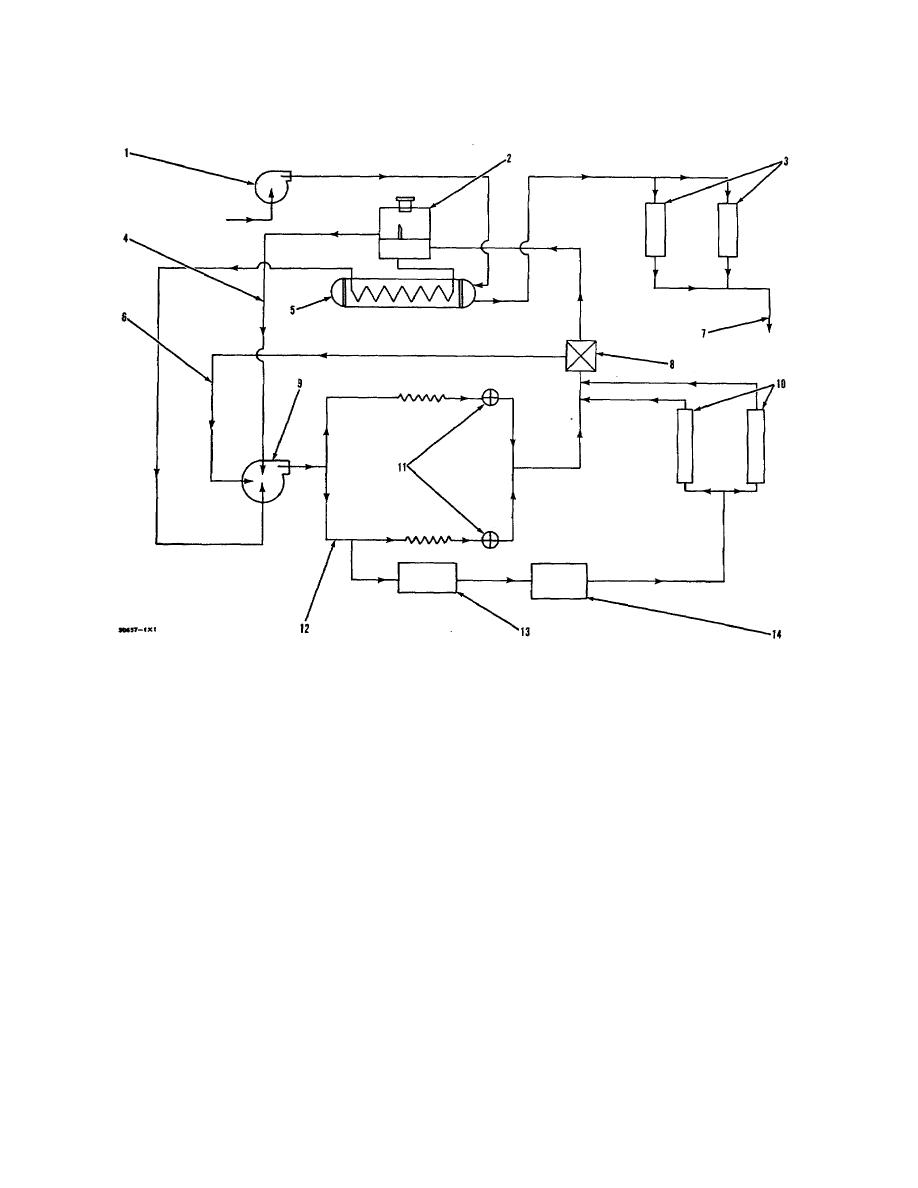
COOLING SYSTEM SCHEMATIC
1. Sea water pump. 2. Expansion tank. 3. Exhaust risers. 4. Shunt line. 5. Heat exchanger. 6. Inside
bypass. 7. Outlet for sea water. 8. Housing for water temperature regulators. 9. Water pump. 10. Water
cooled exhaust manifolds. 11. Orifices between cylinder heads end front cover for the engine. 12. Cylinder
block. 13. Coolant for marine gear oil. 14. Cooler for engine oil.
Water pump (9) is installed on the front face of the
exhaust manifolds the coolant goes to the front cover for
front cover for the engine and is driven by V belts from
the engine.
the crankshaft pulley. As the coolant goes from the water
pump it divides and goes through inside passages in the
From the front cover for the engine the coolant
front cover for the engine to cylinder block (12) and up to
either goes to the inlet for water pump (9) or to expansion
the cylinder heads. From the cylinder heads the coolant
tank (2).
goes forward through orifices (11) to the front cover for
If the coolant is cold (cool) the water temperature
the engine.
regulators (17) will be closed. The coolant will go through
Part of the coolant going to the left side (as seen
inside bypass (6) to water pump (9). If the coolant is
from the flywheel) of cylinder block (12) goes to cooler for
warm the water temperature regulators (17) will be open.
marine gear oil (13) and on to the cooler for engine oil
When the water temperature regulators (17) are open
(14). Both of these oil coolers are in a common housing
they make a restriction in the inside bypass (6) and the
at the top rear of the engine.
coolant goes to the lower part of expansion tank (2).
(Expansion tank (2) is divided into an upper and lower
After the coolant goes through the oil coolers it
compartment by a baffle.) From the lower compartment of
divides and goes to the rear of water cooled exhaust
expansion tank (2) most of the coolant goes through heat
manifolds (10). After going through the water cooled
exchanger (5) and the inlet for water pump (9).
24
|
|
Privacy Statement - Press Release - Copyright Information. - Contact Us |
