 |
|||
|
|
|||
|
Page Title:
COOLING SYSTEM WITH VERTICAL RADIATOR AND SEPARATE SURGE TANK |
|
||
| ||||||||||
|
|
 COOLING SYSTEM
SYSTEMS OPERATION
(Industrial Engines)
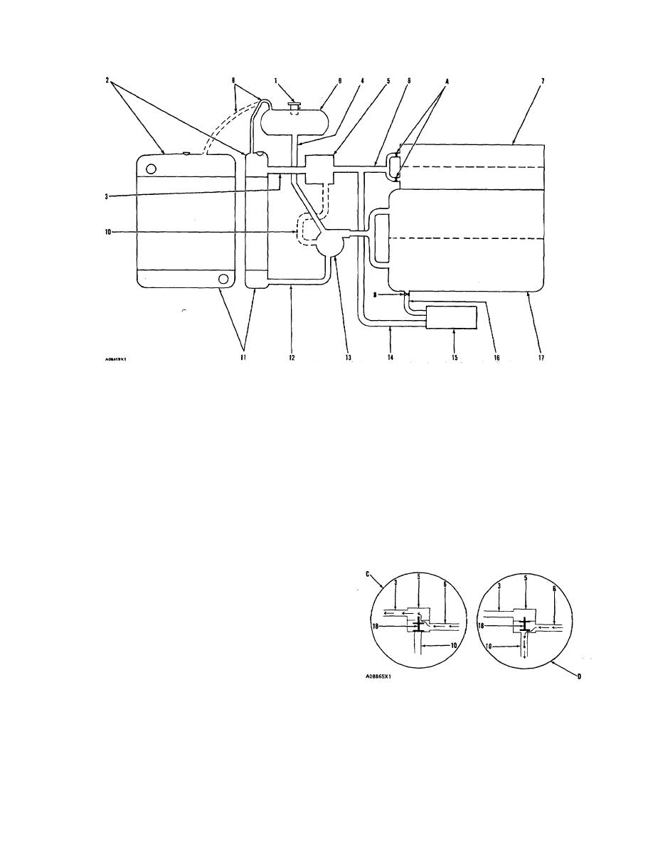
COOLING SYSTEM WITH VERTICAL RADIATOR AND SEPARATE SURGE TANK
1. Radiator cap. 2. Radiator top tank. 3. Radiator top hose. 4. Shunt line. 5. Housing for water temperature
regulators. 6. Return to housing for water temperature regulators. 7. Cylinder heads (two). 8. Vent tube. 9.
Surge tank. 10. Inside bypass. 11. Radiator bottom tank. 12. Radiator bottom hose. 13. Water pump. 14.
Outlet line for oil cooler. 15. Oil cooler. 16. Inlet line for oil cooler. 17. Cylinder block. A. Orifices between
cylinder heads and front cover. B. Orifice in oil cooler outlet.
Water pump (13) is installed on the front face of the
inside bypass (10) to water pump (13). If the coolant is
front cover for the engine and is driven by V belts from
warm the water temperature regulators (18) will be open.
the crankshaft pulley. The inlet opening of water pump
When the water temperature regulators (18) are open
(13) is connected to radiator bottom hose (12). The outlet
they make a restriction in the inside bypass (10) and the
flow of coolant from water pump (13) goes through inside
coolant goes through radiator top hose (3) and into
passages in the front cover for the engine.
radiator top tank (2) or left side tank (2). Coolant then
goes through the core of the radiator to the radiator
bottom tank (11) or radiator right side tank (11) where it is
As the coolant goes from the water pump it divides
again sent through the cooling system.
and goes through the inside passages in the front cover
for the engine to cylinder block (17). Most of the coolant
goes through cylinder block (17) and up to cylinder heads
(7). From cylinder heads (7) the coolant goes forward
through orifices (A) to the front cover for the engine.
Part of the coolant going to the left side (as seen
from the flywheel) of cylinder block (17) goes through
orifice (B) to inlet line (16) and on to oil cooler (15) to
cool the oil for lubrication of the engine and back to the
front cover for the engine through outlet line (14).
FLOW OF COOLANT
From the front cover for the engine the coolant
3. Radiator top hose. 5. Housing (water temperature
either goes to the inlet for water pump (13) or to the
regulators).
6.
Return to housing for water
radiator.
temperature regulators.
10. Inside bypass.
18.
Water temperature regulators (two). C. Flow with
If the coolant is cold (cool) the water temperature
warm coolant. D. Flow with cold coolant.
regulators (18) will be closed. The coolant will go through
22
|
|
Privacy Statement - Press Release - Copyright Information. - Contact Us |
