 |
|||
|
|
|||
|
Page Title:
FUNCTION OF FUEL JUNCTION BLOCK |
|
||
| ||||||||||
|
|
 FUEL SYSTEM
SYSTEMS OPERATION
(75V1-UP, 90N6121-UP)
to the cylinder, the force made by the pressure of
the fuel in the nozzle body will become less. The
force of the spring will then be more than the force
of the pressure of the fuel in the nozzle body.
Valve (8) will move to the closed position.
Valve. (8) is a close fit with the inside of nozzle
tip (13), this makes a positive seal for the valve.
When the fuel is sent to the cylinder, a very
small quantity of fuel will leak by the valve guide.
This fuel gives lubrication to the moving parts of
the fuel injection nozzle.
FUNCTION OF FUEL JUNCTION BLOCK
The location of the fuel junction block (4) is at
the right rear of the engine. The fuel lines from the
fuel tank and the engine connect at fuel junction
block (4).
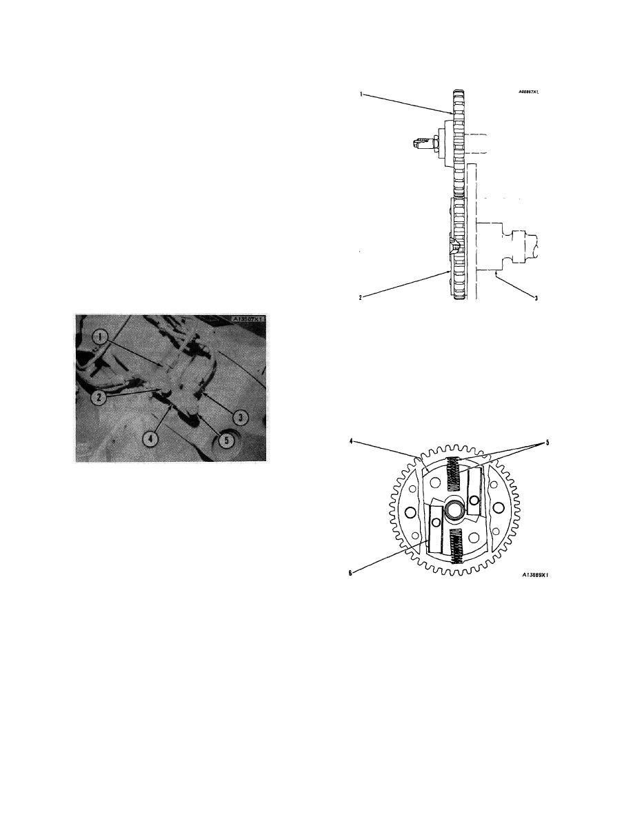
AUTOMATIC TIMING ADVANCE UNIT
1. Gear on camshaft for fuel injection pump. 2. Automatic
timing advance unit. 3. Camshaft for the engine.
angle between the timing advance gear and the two
drive dowels in the drive gear for the engine cam-
shaft. Since the timing advance unit drives the gear
(I) on the camshaft for the fuel injection pump,
the fuel injection timing is also changed.
CONNECTIONS FOR FUEL LINES AT THE
FUEL JUNCTION BLOCK
1. Connection for constant bleed line to housing for fuel
injection pumps. 2. Connection for constant bleed line to
fuel tank. 3. Connection for fuel supply line to fuel filter.
4. Fuel junction block. 5. Connection for fuel supply
line to fuel tank.
AUTOMATIC TIMING ADVANCE UNIT
The automatic timing advance unit (2) is in-
stalled on the front of the camshaft (3) for the
engine. The automatic timing advance unit (2)
AUTOMATIC TIMING ADVANCE UNIT
drive the gear (1) on the camshaft for the fuel
injection pump. This gear is the drive for the cam-
4. Weights. 5. Springs. 6. Slides.
shaft for the fuel injection pump.
The automatic timing advance unit will change
The weights (4) in the timing advance are driven
the timing 5 degrees. This change starts at approxi-
by two slides (6) that fit into notches made on an
mately low idle rpm and is operating up through
angle in the weights. The slides (6) are driven by
the rated speed of the engine. No adjustment can
two dowels which are in the drive gear for the
be made to the automatic timing advance unit.
engine camshaft. As centrifugal force (rotation)
moves weights (4) outward against the force of
Lubrication oil for the timing advance unit
springs (5), the movement of the notches in weights
comes from drilled holes that connect with the
(4) will cause the slides to make a change in the
front bearing for the engine camshaft.
14
|
|
Privacy Statement - Press Release - Copyright Information. - Contact Us |
