 |
|||
|
|
|||
|
Page Title:
CROSS SECTION OF FUEL SYSTEM WITH DASHPOT GOVERNOR |
|
||
| ||||||||||
|
|
 FUEL SYSTEM
SYSTEMS OPERATION
(75V1-UP, 90N6121-UP)
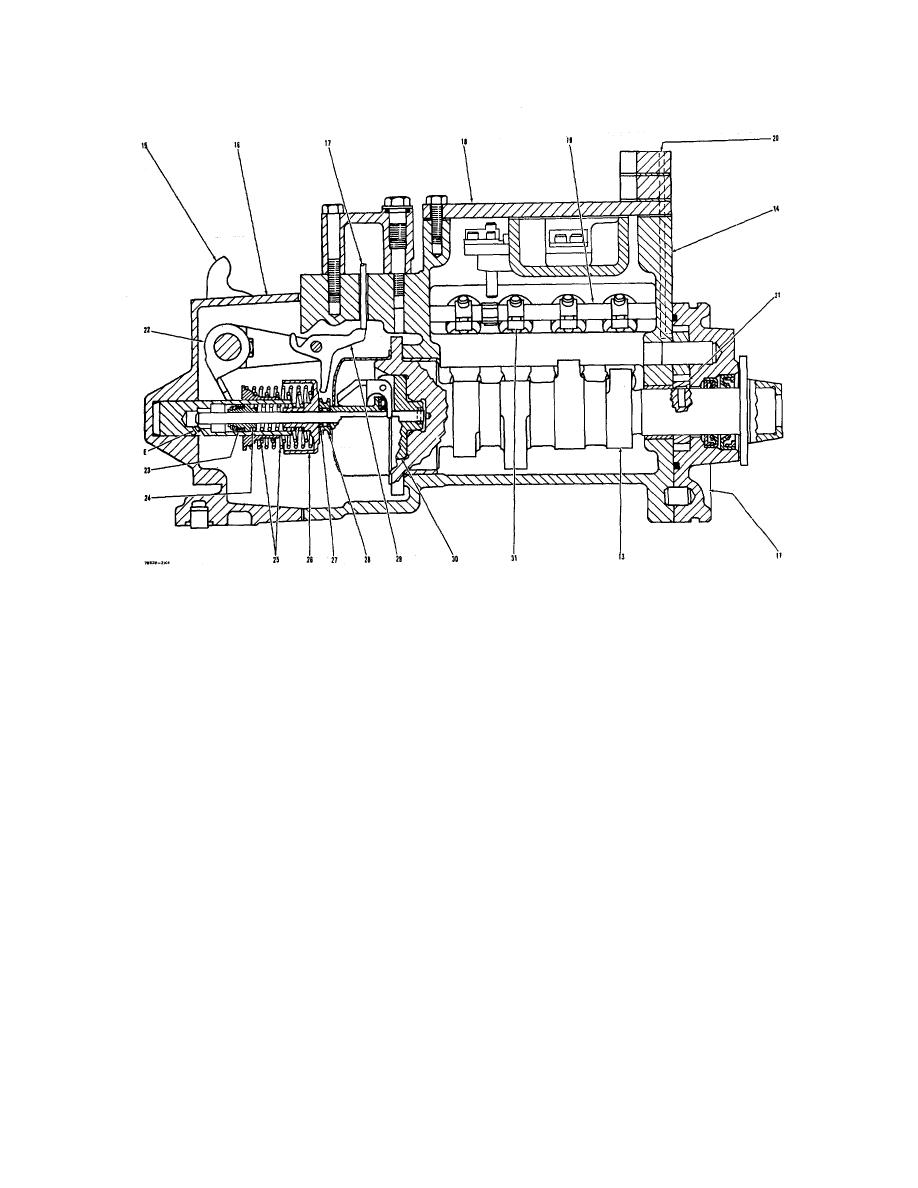
CROSS SECTION OF FUEL SYSTEM WITH DASHPOT GOVERNOR
11. Fuel transfer pump. 13. Camshaft. 14. Housing for fuel injection pumps. 15. Lever. 16. Governor housing. 17. Load stop
pin. 18. Cover. 19. Sleeve control shafts {(two). 20. Inside fuel passage.'21. Drive gear for fuel transfer pump. 22. Lever on
governor shaft. 23. Piston for dashpot governor. 24. Spring for dashpot governor. 25. Governor springs (inner spring is for low
idle: outer spring is for high idle). 26. Spring seat. 27. Over fueling spring. 28. Thrust collar. 29. Load stop lever. 30. Carrier
and governor weights. 31. Sleeve levers. E. Orifice for dashpot.
From fuel transfer pump (11), fuel under
in compression and move thrust collar (28) for-
pressure, fills the housing for the fuel injection
ward. As thrust collar (28) moves forward, the
pumps (14). Pressure of the fuel in housing (14) is
connecting linkage will cause sleeve control shafts
controlled by bypass valve (12). Pressure of the
(19) to turn.' With this movement of the sleeve
fuel at FULL LOAD is 30 5 psi (2.1 0.4
control shafts, levers (31) will lift sleeves (32) to
kg/cm2). If the pressure of fuel in housing (14)
make an increase in the amount of fuel sent to the
gets too high, bypass valve (12) will move (open)
engine cylinders.
to let some of the fuel return to the inlet of fuel
transfer pump (11).
When starting the engine, the force of over fuel-
ing spring (27) is enough to push thrust collar (28)
Lever (15) for the governor is connected by
to the full fuel position. This lets the engine have
linkage and governor springs (25) to the sleeve
the maximum amount of fuel for injection when
control shafts (19). Any movement of lever (22)
starting. At approximately 400 rpm, governor
will cause a change in the position of sleeve control
weights (30) make enough force to push spring
shafts (19).
(27) together. Thrust collar (28) and spring seat
(26) come into contact. From this time on, the
When lever (15) is moved to give more fuel to
governor works to control the speed of the engine.
the engine, lever (22) will put governor springs (25)
11
|
|
Privacy Statement - Press Release - Copyright Information. - Contact Us |
