 |
|||
|
|
|||
|
|
|||
| ||||||||||
|
|
 CENTER JOINT
 REMOVAL:
1. Park machine on level surface, set parking
brake and lower blade.
2. Remove ignition key and disconnect battery
cables.
3. Remove front and rear fenders.
4. Raise machine so that wheels clear the
ground and securely block the machine.
5. Remove cleaner teeth and wheels.
6. Lower machine so that axles are on the
ground and block machine securely.
7. Remove front and rear floor plates.
8. Close the fuel valve at the fuel tank and
disconnect and cap fuel supply and fuel return hoses
at the engine. Remove hose support bracket.
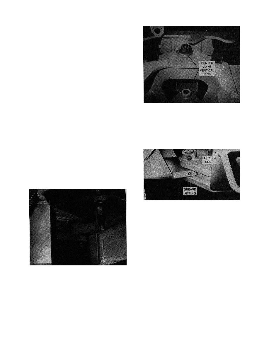
Center Joint Vertical Pins
9. Secure dozer blade at its lowest position,
with control lever secured in the HOLD position.
13. Remove locking bolt and press out lower
Disconnect and cap dozer hoses from the valve.
vertical pin. This pin will remove In either direction.
Note: It is recommended to block the control lever In
14. With the rear frame section secure, the front
the HOLD position to prevent loss of hydraulic oil
frame section may now be moved forward and
resulting from accidental movement of the lever.
blocked to allow center Joint assembly to be
10. Remove cotter pins and both front steering
removed.
cylinder clevis pins.
11. Disconnect the drive shaft from the center
joint yoke end.
12. With the front and rear frame sections
securely blocked, remove cotter pin, slotted nut and
washer retaining the top vertical pin. This pin must
then be pressed DOWNWARD for removal. Care
should be taken not to damage the thread on
removal.
Lower Vertical Center Joint Pin
15. Remove drive shaft assembly and drive
shaft center bearing from center joint assembly.
16. With the center joint assembly secured,
remove locking bolt and press out horizontal pin
towards the REAR of the machine. The pin cannot
be pressed out towards the front as It will contact the
front axle housing before it is clear.
17. Remove horizontal thrust washers and lift
out the center joint assembly. As the assembly Is
being lifted out, the top must be tilted to the rear to
allow the lower bearing plate to clear the front frame.
Top Center Joint Vertical Pin
Rev. 760501
K300
30-1.1
|
|
Privacy Statement - Press Release - Copyright Information. - Contact Us |
