 |
|||
|
|
|||
|
Page Title:
Engine Air Intake For Turbocharged Engines |
|
||
| ||||||||||
|
|
 TM 5-3835-222-BD
drive the turbocharger to compress air and force it into the cylinder under pressure. The engine air
intake system is therefore vacuum and pressure. Assessment and repairs to turbocharged air system
should therefore be based on the rules above for the system up to the turbocharger inlet. For the
outlet, the repairs should seal so that the air pressure does not escape. Because the turbocharger
depressurization.
4-8. Engine Air Intake For Supercharged or Tubosupercharged Engines. Supercharged engines
use a mechanical system to drive the air intake compressor. The supercharger is usually mounted
directly on the intake manifold or engine block. Some Detroit Diesel models are turbosupercharged.
Damage assessment and repair to these engines require the same techniques and precautions that
turbocharged engines require for the vacuum and pressurized parts of the air intake system.
Because superchargers are mechanically driven, repairs to the drive system will usually require
repair parts.
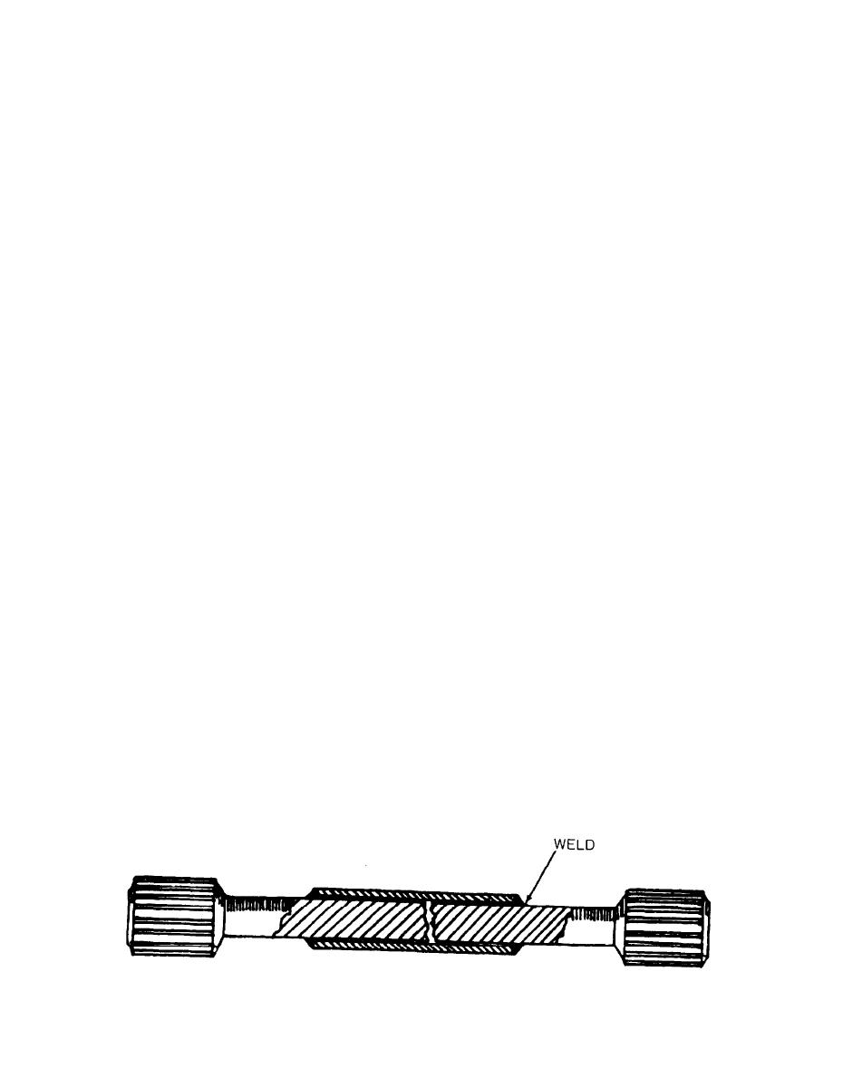
4-9. Blower Drive Shaft Broken. The blower provides pressurized air to the engine air box. The
blower is driven by a drive shaft (quillshaft) which acts as the fuse for the supercharger system. The
shaft shears when it is overloaded to protect the blower from damage. The shaft can be repaired
if a new part is not available.
Limitations:
Blower may be damaged.
l
Personnel/Time Required:
1 soldier - 1.0 hr.
l
Materials/Tools:
Welding Equipment
l
Deleted.
l
Procedural Steps:
a. Gain access to the drive shaft and remove both broken ends.
b. Use heavy steel tubing, or machine a sleeve so that the proper length is maintained.
c. Install sleeve or tube on shaft. Ensure that the proper length is maintained.
d. Weld ends of sleeve to shaft.
Change 1 4-3
|
|
Privacy Statement - Press Release - Copyright Information. - Contact Us |
