 |
|||
|
|
|||
|
Page Title:
LOCATION AND DESCRIPTION OF MAJOR COMPONENTS. |
|
||
| ||||||||||
|
|
 TM 3-4230-209-30&P
1-2
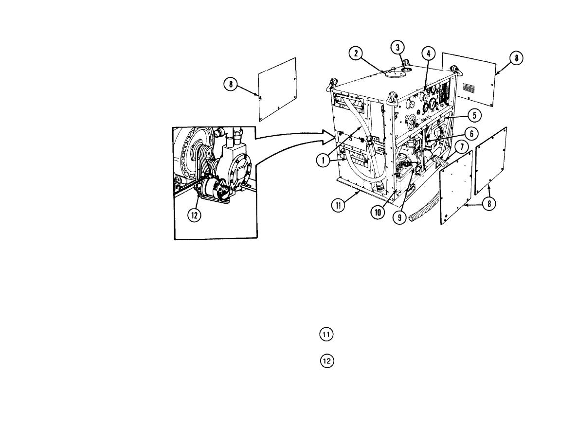
1-6. LOCATION AND DESCRIPTION OF MAJOR COMPONENTS.
a. Pump Unit.
“
Œ
COVER PANEL ASSEMBLIES. Provide protection from elements,
HOSE ASSEMBLIES. Discharge fluid. Mounted on fixed reel assemblies.
access to components, and, when removed, ventilation for the gasoline
engine.
PRIME DETERGENT TANK. A 10 gallon tank. Stores foam or deter-
”
gents for mixing in the tank unit and stores water for priming the pump.
CENTRIFUGAL PUMP. Provides the means of pressurizing and trans-
Ž
ferring fluids from sources to tank unit, heater, or discharge hoses.
ENGINE FUEL TANK. Holds 20 gallons of fuel for gasoline engine.
•
STORAGE BATTERY. Supplies current to start the gasoline engine.
CONTROL PANEL ASSEMBLY. Contains controls and instruments for
pump unit.
SKID BASE SUBASSEMBLY. Provides base for pump unit subassem-
bly, alternator, and gasoline engine.
GASOLINE ENGINE. A 20 hp engine. Drives the pump unit and
ALTERNATOR/GENERATOR. Powered by a V-belt and a pulley from
‘
gasoline engine. Provides current to the water heater through the
FRAME ASSEMBLY. Supports components of the pump unit.
engine alternator junction box behind the HEATER RECEPTACLE AND
’
SWITCH.
EXHAUST PIPES. Pipe exhaust fumes away from the engine assembly.
Stored on top of the tank unit assembly.
|
|
Privacy Statement - Press Release - Copyright Information. - Contact Us |
