 |
|||
|
|
|||
|
|
|||
| ||||||||||
|
|
 TM 3-1040-279-12&P
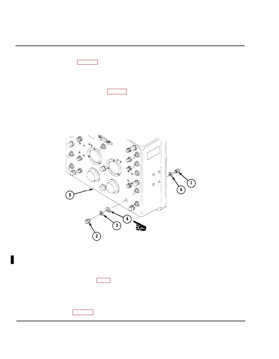
4-28 CONTROL PANEL ASSEMBLY (CONT).
d. Indicator Lights.
REMOVAL
Remove panel cover (P. 4-110).
1.
NOTE
Removal and installation procedures are the same for all indicator lights.
When replacing left side POWER and FUEL indicator lights, circuit breaker
CB1 must be removed first (P. 4-113).
Tag and unsolder electrical connections from indicator socket (1).
2.
Unscrew indicator lens (2) from indicator socket (1).
3.
Remove nut (3) and lock washer (4) from indicator socket (1) and remove indicator socket from
4.
instrument panel (5). Remove nut (6) from indicator socket (1).
INSTALLATION
Screw on nut (6) approximately in. (6mm) onto indicator socket (1).
1.
2.
Install indicator socket (1) in instrument panel (5) and secure with nut (3), and lock washer (4).
Solder electrical connections to indicator as tagged. For two wire connections, place insulation
3.
sleeving (Item 7C, App E) over both leads. Solder one lead to indicator pin. Solder second lead to
first lead 0.125 to 0.250 inches from indicator pin. Pull insulation sleeving over soldered connection
and heat shrink.
Screw indicator lens (2) onto indicator socket (1).
4.
5.
Install panel cover (P. 4-110).
4-114
Change 4
|
|
Privacy Statement - Press Release - Copyright Information. - Contact Us |
