 |
|||
|
|
|||
|
|
|||
| ||||||||||
|
|
 TM 3-1040-279-12&P
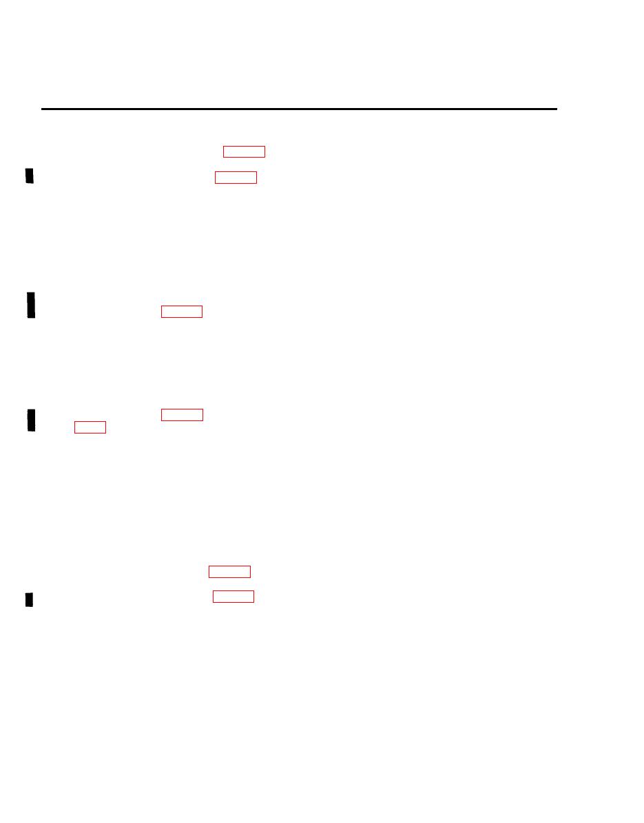
4-11 COVER ASSEMBLY (CONT).
d. Cable Assembly 5J1.
REMOVAL
1. Remove equipment container (P. 4-68).
2. Disassemble cover assembly (P. 4-36).
3. Remove four screws (l), washers (2) and nuts (3) and remove cable assembly (4) from cover
assembly (5).
4. Remove eight screws (6) and washers (7) and remove equipment container panel (8).
5. Remove four screws (9), washers (10), and lockwashers (11) securing terminal bracket assembly
(12) to gain access to terminal bracket assembly.
6. Remove electrical connections of 5J1 from top terminals of terminal board (13). See smoke
generator wiring (P. 4-34).
7. Remove cable assembly (4) from equipment container (14).
INSTALLATION
1. Install cable assembly (4) in equipment container (14) and attach electrical connections. See smoke
generator wiring (P. 4-34). Coat terminal board screw threads with sealing compound (Item 11A,
2. Position terminal bracket assembly (12) in equipment container (14) and secure terminal bracket
assembly (12) with four screws (9), washers (10) and lockwashers (11).
3. Secure cable assembly (4) to cover assembly (5) with four screws (l), washers (2) and nuts (3).
4. Make sure switches on terminal bracket are in OFF (down) position.
5. Position equipment container panel (8) on equipment container (14) and secure with eight screws
(6) and washers (7).
6. Reassemble cover assembly (P. 4-37).
7 . Install equipment container (P. 4-69).
|
|
Privacy Statement - Press Release - Copyright Information. - Contact Us |
