 |
|||
|
|
|||
|
Page Title:
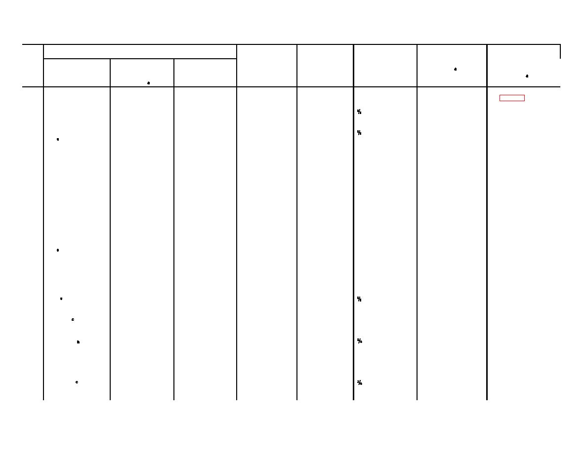
Alignment Chart, Receiving Set, Radio AN/PRR-9(XE-9) |
|
||
| ||||||||||
|
|
 TM 11-6625-937-12
Control settings of
ID-1189(XE-2)/PR
RECVR
FREQUENCY
P8A
P5A
Receiver
Adjustments
Adjust
Step
TEST
MC
TEST
RECVR
control
(figs. 3-17 and 3-18)
for
No.
FUNCTION
SIG.
PROBE
OUTPUT
1
------
-------
--------
--------
----------
-------------
Holes B, C, D
Per fig. 3-18
2
OSCc
--------
--------
TP 1
----------
cw
Hole A
Max meter
indication.
3
COARSE
Max cw
Approx. new
TP 2
----------
cw
FREQUENCY
Preset FRE
RF.
operating
MC.
QUENCY MC
frequency.
to approximate
new operating
frequency, and
then make fine
adjustment for
maximum
meter indica-
tion.
Do not change the
setting of the
FREQUENCY MC
control afterstep No.
3.
4
COARSE
Max cw
----------
Removed
Headset
Clockwise
Hole C----------
Min meter indi-
RF.
cation. Reduce
RCVR TEST
SIG. ccw to
keep meter
pointer on-
scale.
5
OSC ------------
-----------
--------------
TP1
-------------
cw
Hole A-----------
Max meter indi-
cation.
6
FINE RF.
Max ccw
------------
Removed
Headset
Clockwise
Hole C-----------
Min. Meter indi-
from
jack
unsquelched
cation.
7
SQUELCH
------------
-------------
TP1
Headset
cw
Hole E max
Upscale meter
jack
Squelched.
ccw, then
indication
slowly cw
until indica-
tion.
8
SQUELCH
------------
---------------
TP1
Headset
cw
Meter pointer
jack.
(No change
(No change
should swing
from 7).
From 7).
downscale.
Change 2
3-13
|
|
Privacy Statement - Press Release - Copyright Information. - Contact Us |