 |
|||
|
|
|||
|
Page Title:
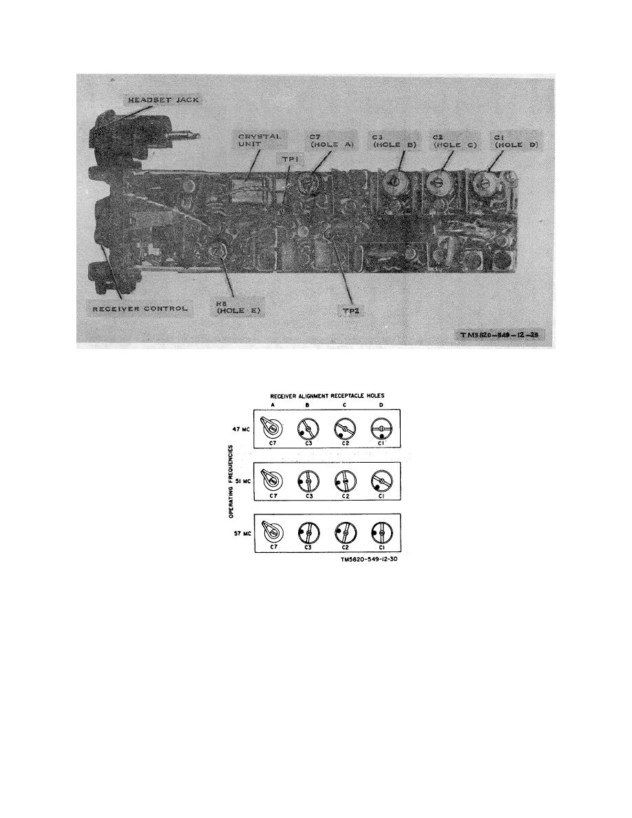
Figure 3-6. Receiving Set, Radio AN/PRR-9, alignment adjustments. |
|
||
| ||||||||||
|
|
 TM 11-6625-937-12
Figure 3-6. Receiving Set, Radio AN/PRR-9, alignment adjustments.
Figure 3-7. Receiving Set, Radio AN/PRR-9, approximate trimmer capacitor settings for alignment.
l. Turn the ID-1189/PR FUNCTION switch to RCVR-FINE RF. Turn the RCVR TEST SIG. rotary switch to its
maximum counter-clockwise position. Place the RCVR OUTPUT plug in the headset jack of the AN/PRR-9 electronic
assembly (fig. 36). Adjust AN/PRR-9 capacitor C1 under hole D for a minimum indication on the meter.
m. Turn the AN/PRR-9 receiver control t OFF and then turn it slowly clockwise to a position equal to one-half of full
rotation, to adjust the receiver for squelch operation. Turn the ID-1189/PR FUNCTION switch to RCVR- SQUELCH.
Leave the RCVR OUTPUT plug in the headset jack. Turn the adjustment screw under hole E fully counterclockwise. Turn
the adjustment screw under hole E clockwise until the meter indication drops to zero; continue to turn the adjustment
screw clockwise an additional one-eighth turn. Turn the FUNCTION switch repeatedly from RCVR-ANT. to RCVR-
SQUELCH and carefully observe the swing of the meter needle. Turn the adjustment screw under hole E until repeated
turning of the FUNCTION switch from RCVR-ANT. to RCVR-SQUELCH produces a rapid swing of the meter needle to
midscale followed by a drop- off to zero. Counterclockwise rotation of the adjustment screw in hole E will increase the
meter swing.
Change 2
3-7
|
|
Privacy Statement - Press Release - Copyright Information. - Contact Us |
