 |
|||
|
|
|||
|
|
|||
| ||||||||||
|
|
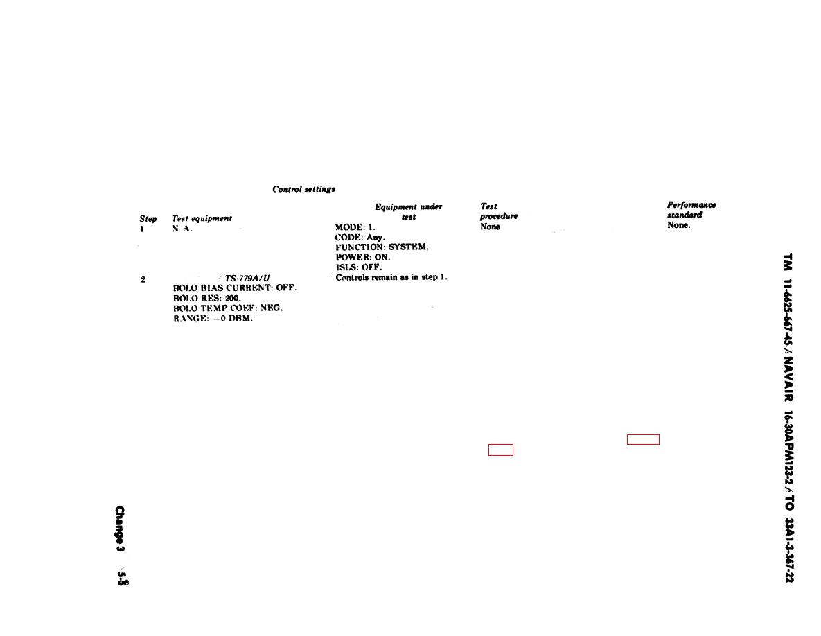 5-4. Transmitting Power Test
a. Test Equipment Required
b. Test Connections and Conditions.
(1) Connect the equipment as indicated in c below.
(2) Connect test point A4TP5 to ground (module A4 at the rear of test set).
c. Procedure.
CAUTION
The teat equipment settings must be
performed before the MX-2144A/U,
is connected to avoid equipment
damage.
a. None.
a. Connect the MX-2144A/U to the TS-
779A/U.
b. None.
b. Adjust the TS-779A/U as follows:
(1) Set the BOLO BIAS CURRENT
Switch to 10-16 MA.
(2) Set the LINE-POWER switch to
O N , and permit a 15-minute
warmup.
(3) Adjust the ZERO SET COARSE
A N D FINE controls to zero
meter.
C. None.
grounded.
d. Connect the MX-2144A/U to the test set d. 6 1dbm.
PROBE jack. Observe the power in-
dication.
e. None.
e. Disconnect the ground from test point
A4TP5, and connect test point A4TP4
t o g r o u n d . Disconnect the MX-
2144A/U.
|
|
Privacy Statement - Press Release - Copyright Information. - Contact Us |
