 |
|||
|
|
|||
|
Page Title:
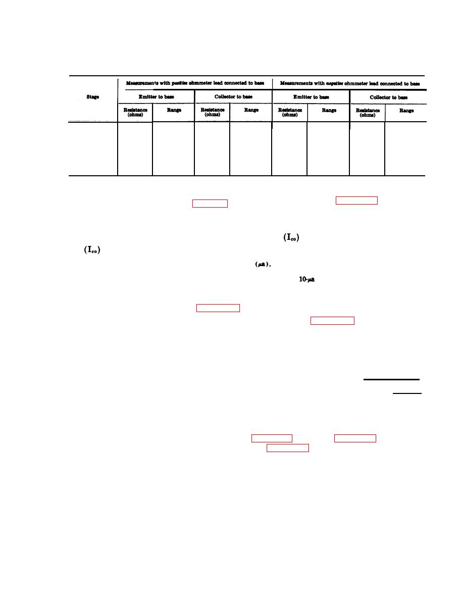
Out-of-Circuit Transistor Tests |
|
||
| ||||||||||
|
|
 TM 11-6625-667-45/NAVSHIPS 0969-249-8010/NAVAIR 16-30APM123-2/TO 33A1-3-367-22
(11) In-circuit resistance measurements of module A16. Unless specified otherwise, all transistors are
type 2N706. All measurements should be within 50 percent of values shown. Transistor Q3 is not
listed because it is not accessible.
10K
R X 10K
R X 10K
10K
780K
R
X
10K
Q1 (2N2222) ---
R
X
10K
750K
10K
R X 10K
R X 10K
11K
Q2 (2N2222) ---
700K
R
X
10K
R
X
10K
680K
10K
R X 10K
R
X
10K
RX100
58K
740
A2Q1---------
R
X
10K
58K
22K
10K
R X 10K
RX100
R
X
10K
720
22K
A2Q2----------
R
X
10K
11K
R
X
10K
620
RX100
RX100
620
R
X
10K
11K
A2Q3 (2N1485)-
b. Leakage Test. Connect the transistor and the
3-9. Out-of-Circuit Transistor Tests
TS-352B/U as shown in figure 3-20. The resultant
Perform as many in-circuit tests (para 3-8) as
value should be equal to, or less than, the maxi-
practical before removing wired-in transistors
mum allowable leakage current (I.c o) for that
When a transistor tester is not available an
particular transistor as shown in the Maximum
ohmmeter may be used to test the emitter and col-
leakage
column (d below).
lector diode condition (a below), maximum leak-
age
(b below), and grounded emitter and
utilized for measuring current as low as 1 microampere
current gain (dc beta) (c below).
any readable deflection in this range can be assumed
to be in excess of the permissible maximum leakage cur-
fied to avoid transistor damage. Set ohmeter
rent. Since the
reading is also on the low end of the
range before making any connections.
meter scale and similarly difficult to read, any indication
significantly higher (above 20 a) can be assumed to be
a. Emitter and Collector Diode Test. Use the
too great.
chart (d below) in conjunction with figure 3-19,
c. Gain Test. Connect the transistor and ohmme-
to determine the condition of the emitter and col-
ter as shown in figure 3-21. Note the ohmmeter
lector diodes of the transistor under test. Ohmme-
indication. The grounded emitter current gain (dc
ter connections, to measure forward and reverse
beta) can then be computed from the appropriate
resistance of either emitter or collector diodes of
formula below and compared with the values
NPN transistors, are shown in the illustration.
listed in the Minimum gain dc beta column (d
Only NPN-type transistors are used in this equip-
below).
ment. If the needle of the ohmmeter creeps slowly
12,000
Low-power transitions: Dc beta=
toward a lower value while forward or reverse
Ohmmeter reading
High-power transistors: DC beta= 1,200
resistance measurements are being performed, the
--
Ohmmeter reading
transistor is defective.
Note. A transistor that indicates normal during gain
Caution: If either of the transistor junc-
tests may still have excessive leakage.
tions (diodes) is shorted, as indicated by low
d. Readings. The following chart lists readings
dc resistance of both directions do not perform
taken with the TS-352B/U connected as shown in
the leakage test (b below) as the ohmmeter may
be damaged.
and figure 3-21 (gain, dc beta).
3-39
|
|
Privacy Statement - Press Release - Copyright Information. - Contact Us |
