 |
|||
|
|
|||
|
Page Title:
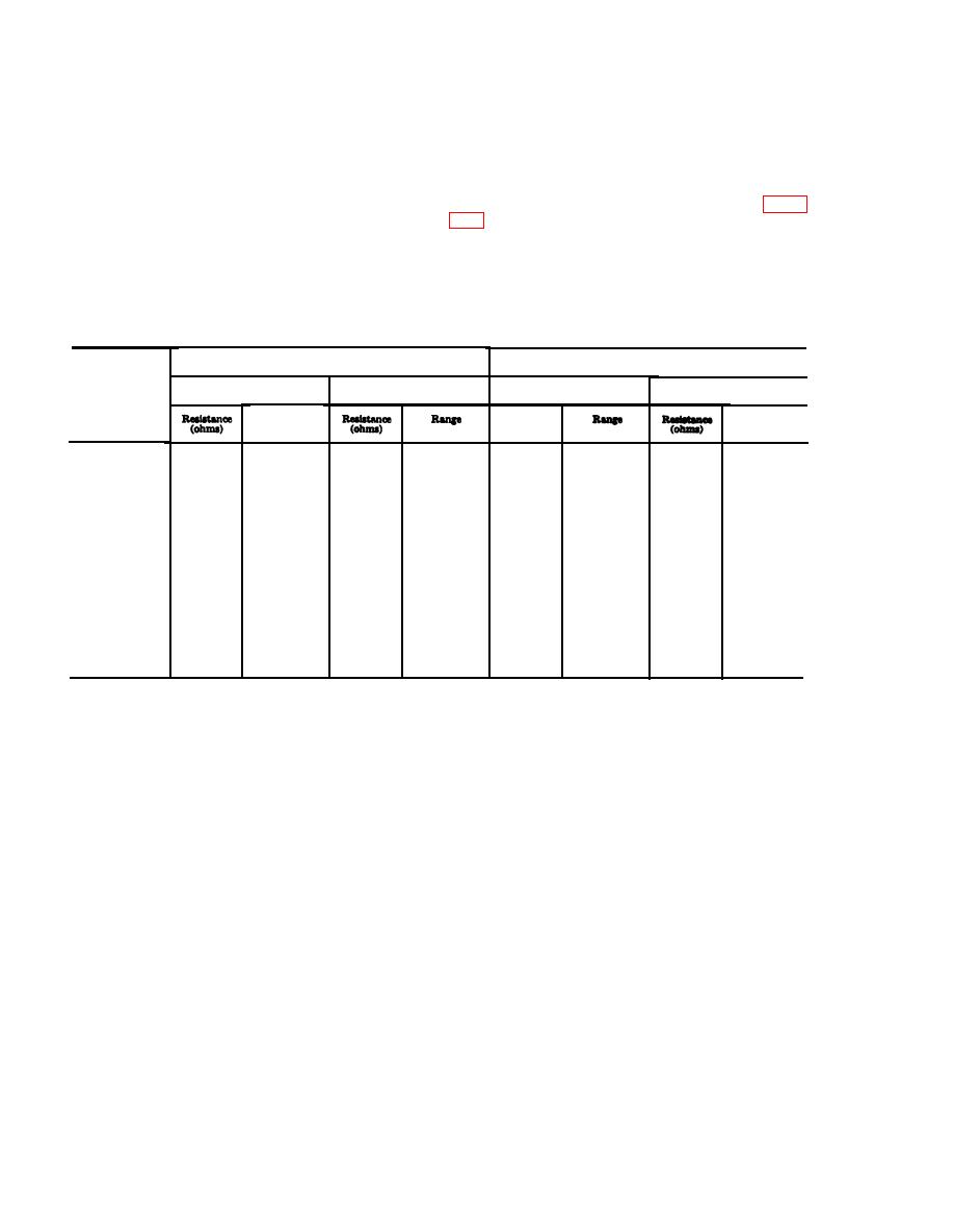
Figure 3-18. Decoder module A12 voltage and resistance diagram.-CONT./ |
|
||
| ||||||||||
|
|
 TM 11-6625-667-45/NAVSHIPS 0960-249-8010/NAVAIR f6-30APM123-2/TO 33A1-3-367-22
charts in (1) through (11) below are resistance
than if taken with the ohmmeter on the RX100
measurements taken of the emitter and collector
range. When in doubt about the result of resistance
with the transistors connected in the circuit. The
measurements, check a known good equipment for
measurements
are
made
with
correct readings The readings in b below were
TS-352B/U. These readings will be valid only if
taken with each module removed from the equip-
the same type ohmmeter is used and polarity and
ment. First measure between the base and the emit-
range scales are strictly adhered to. Refer to figure
ter and between the base and the collector with the
positive ohmmeter lead connected to the base, and
(1) In-circuit resistance measurements of
then measure between the base and the emitter and
module A4. All transistors except G13 (2N2222),
between the base and the collector with the nega-
are type 2N706. All measurements should be with-
tive ohmmeter lead connected to the base.
in 50 percent of values shown.
b. In-Circuit Resisance Charts. Listed in the
Measurements with positive ohmmeter lead connected to base
Measurments with negative ohmmeter lead connected to base
Emitter to base
Emitter to base
Collector to base
Stage
Collector to base
Range
Resistance
Range
(ohms)
Q1------------
24K
R
X
10K
R
X
100
880
R
X
100
710
9K
R
X
100
R
X
10K
R
X
10K
Q2------------
870
R
X
100
730
14K
33K
R
X
100
R
X
10K
R
X
100
Q3------------
860
R
X
100
8K
23K
630
R
X
100
Q4------------
R
X
10K
R
X
100
850
R
X
100
23X
8K
670
R
X
10
880
R
X
100
Q5------------
R
X
10K
R
X
100
8K
33K
710
R
X
100
R
X
10K
R
X
10K
Q6------------
35K
870
R
X
100
710
17K
R
X
100
R
X
100
880
24K
R
X
10K
Q7------------
R
X
100
R
X
100
8500
720
R
X
10K
470K
R
X
10K
Q8------------
840
R
X
100
750K
700
R
X
100
R
X
10K
R
X
100
Q9------------
R
X
100
7K
10K
850
710
R
X
100
R
X
10K
Q10-----------
R
X
10K
870
R
X
100
35K
R
X
100
17K
730
R
X
10K
R
X
100
Q11-----------
R
X
100
850
R
X
100
34K
8500
650
630
R
X
100
R
X
100
780
Q12-----------
R
X
100
840
1100
R
X
100
830
R
X
10K
R
X
100
Q13 (2N2222)..
678K
R
X
100
1200
R
X
100
820
( 2 ) In-circuit resistance measurements of module A5. All transistor, except Q7 and Q11, are type
2N706. All measurements should be within 50 percent of values shown.
3-34
|
|
Privacy Statement - Press Release - Copyright Information. - Contact Us |
