 |
|||
|
|
|||
|
Page Title:
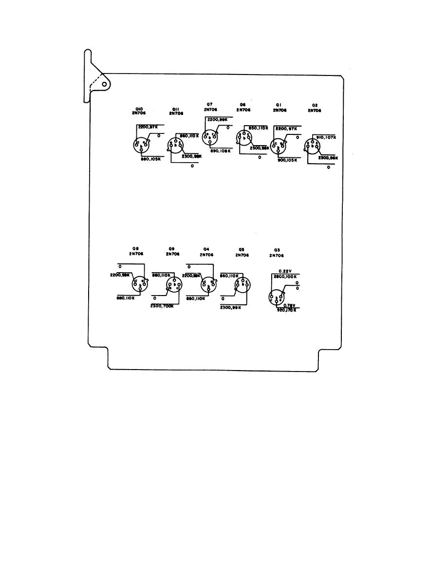
Figure 3-15. Decoder module A9 voltage and resistance diagram. |
|
||
| ||||||||||
|
|
 TM 11-6625-667-45/NAVSHIPS 0969-249-3010/NAVAIR 14-30APM123-TO 33A1-3-367-22
NOTES:
UNLESS OTHERWISE INDICATED
1. ALL MEASUREMENTS ARE FROM DESIGNATED TERMINAL TO CHASSIS. VOLTAGES SHOWN
ABOVE LEAD LINES, RESISTANCES BELOW. VOLTAGES SHOWN FOR NON-DIGITAL CIRCUITS ONLY
2. VOLTAGES MEASURED WITH MULTIMETRER ME-26/U, NO SlGNAL CONDITIONS
3. REMOVE MODULE FORM EQUIPMENT TO MAKE RESISTANCE MEASUREMENTS. MAKE
MEASUREMENTS WITH MULTIMETER TS-352/U, Rx 100 RANGE FOR INDICATED RESISTANCES
10K OR BELOW, AND Rx 10K RANGE FOR THOSE ABOVE 1OK. FIRST READING WITH
NEGATIVE LEAD TO CHASSIS, SECOND WITH LEADS REVERSED
4. PREFIX REFERENCE DESIGNATIONS WITH A9
TM6624-667-35-30
Figure 3-15. Decoder module A9 voltage and resistance diagram.
3-30
|
|
Privacy Statement - Press Release - Copyright Information. - Contact Us |
