 |
|||
|
|
|||
|
Page Title:
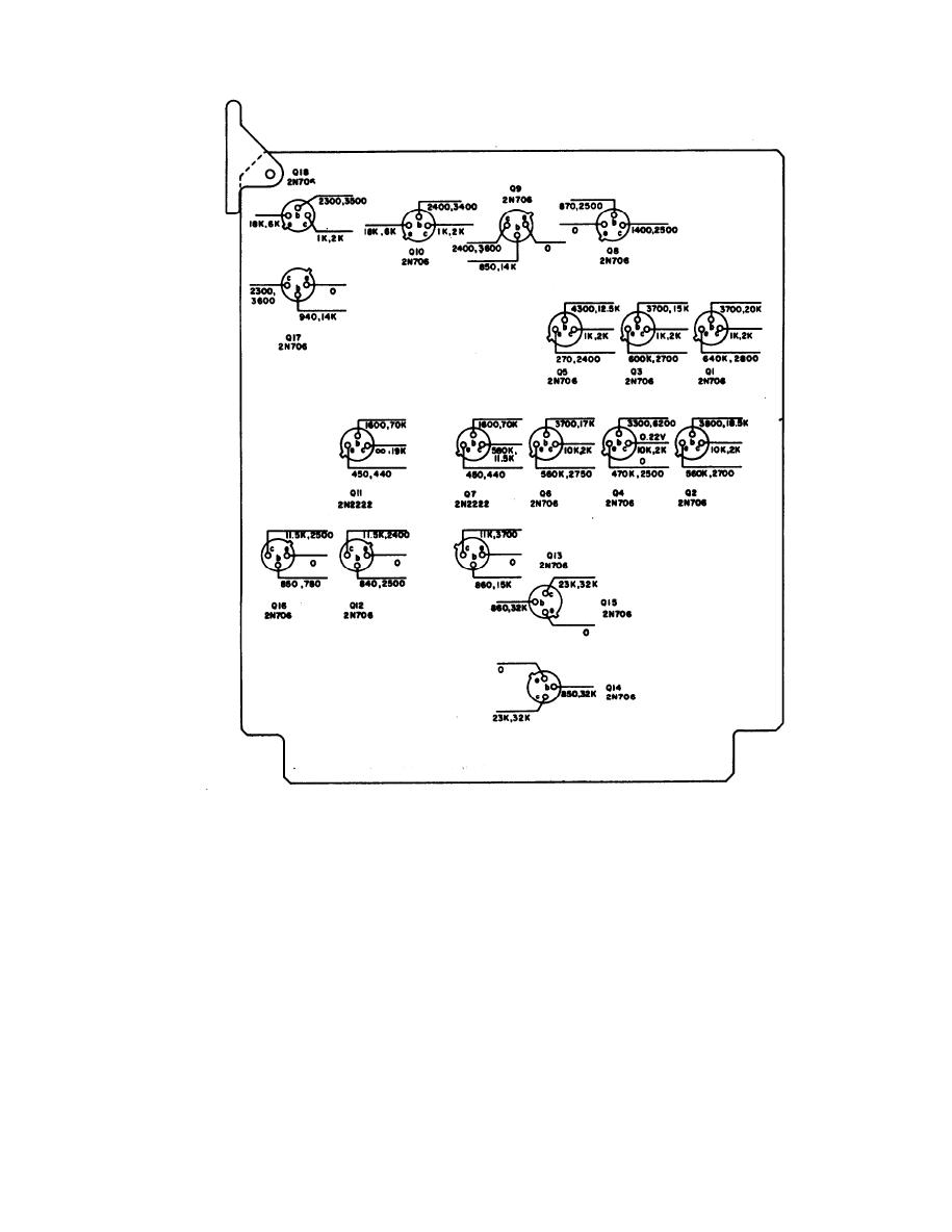
Figure 3-12. Encoder module A5 voltage and resistance diagram |
|
||
| ||||||||||
|
|
 TM 11-6625-667/NAVSHIPS 0969-249-8010/NAVAIR 16-30APM123-2/TO 33A1-3-367-22
NOTES:
UNLESS 0THERWISE INDICATED
1. ALL MEASUREMENTS ARE FROM DESIGNATED TERMINAL TO CHASSIS. VOLTAGES SHOWN
ABOVE LEAD LINES, RESISTANCES BELOW. VOLTAGES SHOWN FOR NON-DIGlTAL ClRCUTS ONLY
2. VOLTAGES MEASURED WITH MULTIMETER ME-26/U, NO SIGNAL CONDITIONS
3. REMOVE MODULE FROM EQUPMENT TO MAKE RESISTANCE MEASUREMENTS. MAKE
MEASUREMENTS WITH MULTIMETER TS-352/U, Rx 100 RANGE FOR INDICATED RESISTANCES
10K OR BELOW. AND Rx 10K RANGE FOR THOSE ABOVE 10K. FIRST READING WITH
NEGATIVE LEAD TO CHASSIS, SECOND WITH LEADS REVERSED
TM6625-667-35-24
4. PREFIX REFERENCE DESIGNATIONS WITH A5
Figure 3-12. Encoder module A5 voltage and resistance diagram
3-27
|
|
Privacy Statement - Press Release - Copyright Information. - Contact Us |
