 |
|||
|
|
|||
|
Page Title:
PIUS 28-Volt Dc Supply, Stage Analysis |
|
||
| ||||||||||
|
|
 TM 11-6625--667-45/NAVSHlPS 0969-249-8010/NAVAIR 16-30APM123-2/TO 33A1-3-367-22
dc is coupled by inductor 1.1 to the test set modules.
put of the Schmitt trigger to go low. Thus, the ac-
Regulator diode A 15VR1 provides regulation.
cept gate is gated on and causes the accept emitter
follower to conduct through ACCEPT indicator
2-16. Twelve-Volt Regulator Module A13,
A15DS1. If a reply is incorrect, the low 1 output
Stage Analysis
of DFF5 has no effect and the emitter-follower
output is high; thus, capacitor A12C8 is charged
This module contains two separate regulates a
through A12R18 for this period. When 50 or fewer
+ 12-volt and a 12-volt circuit. The circuit per-
replies are correct., the capacitor is charged to a
form as follows:
high level and causes the 0 output of the Schmitt
a. + 12-Volt Regulator. This regulator consists
trigger to go low. The reject gate is gated on and
of transistors Q1, Q2. and Q8. Transistor Q1 is the
causes the reject emitter follower to conduct
series power regulator stage. Assuming a constant
through REJECT indicator A15DS2. Note that
28-volt input is present, Q1 provides and effective
50 to 80 percent correct replies can cause alter-
16-volt drop in the line since it is in series, This
nate triggering of the Schmitt trigger. This in
results in a 12-volt emitter output, and its conduc-
turn will result in alternate accept and reject
t ions is regulated by stage Q3. This stage (Q3) is
indications.
normally conducting and the collector output is
coupled to the base of Q1 by emitter follower Q2.
2-15. PIUS 28-Volt Dc Supply, Stage Analysis
The bias of Q3 is held constant by the emitter-base
bias arrangement. The emitter voltage of Q8 is
The +28-volt dc power supply provides the main
held at 4.7 volts by regulator diode VR2. Base bias
B+ power to the test set. It is a conventional
is held at 5.3 volts by regulator diode VR3 and
bridge rectifier, with diodes A15CR1 through
resistor R5. Diodes CR1 through CR5 in the base
A15CR4 providing the rectification. The 115-volt
circuit serve as a series clamp. An increase in the
ac, primary power source is applied from the
+28-volt input voltage increases the conduction of
POWER jack through POWER switch A15S3 to
Q3 through load resistors R2 and R3. This action
decreases the collector voltage of Q3 and the cor-
stepdown transformer T1. The rectified +28 volts
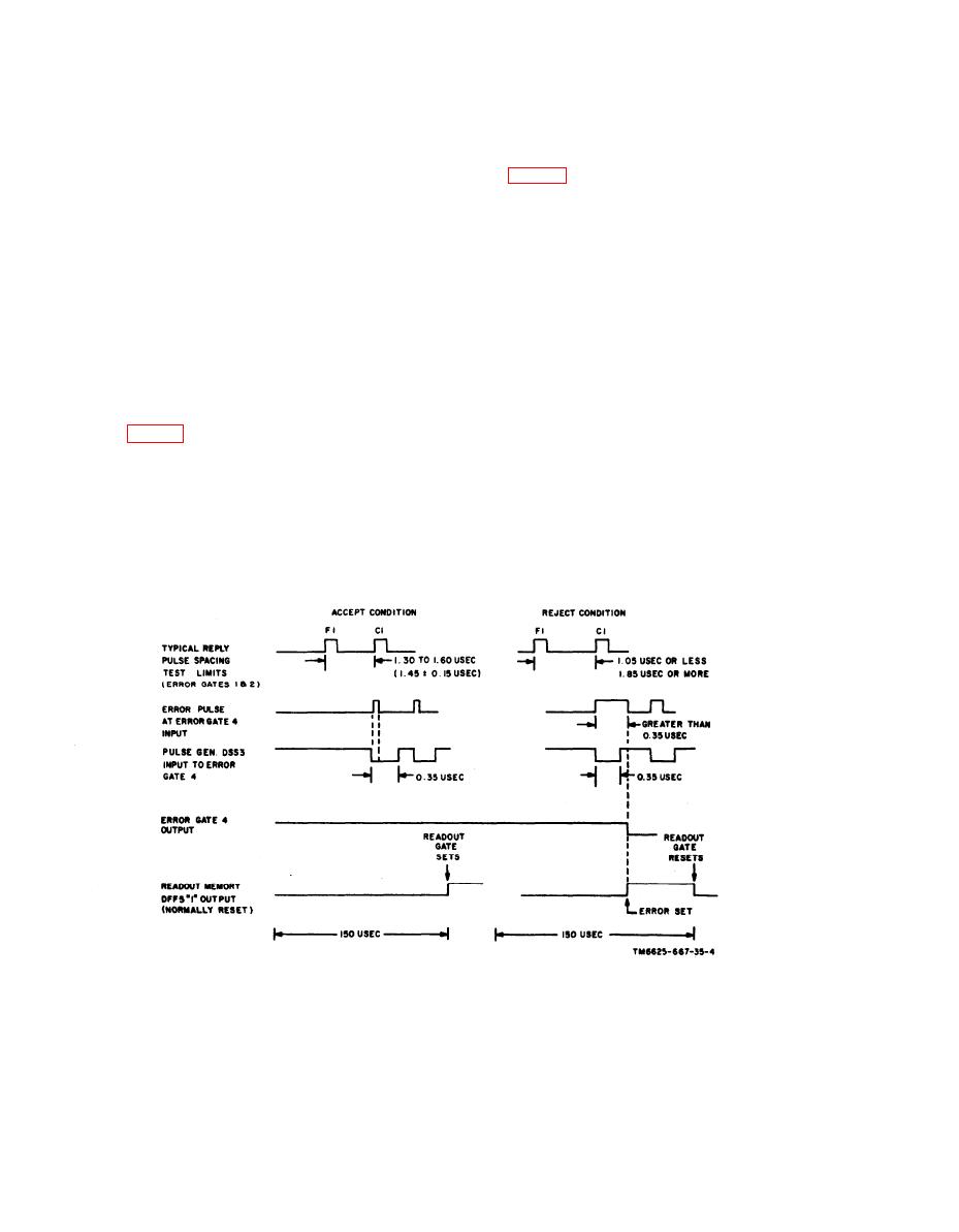
Figure 2-13. Error dectection timing diagram.
2-24
|
|
Privacy Statement - Press Release - Copyright Information. - Contact Us |
