 |
|||
|
|
|||
|
Page Title:
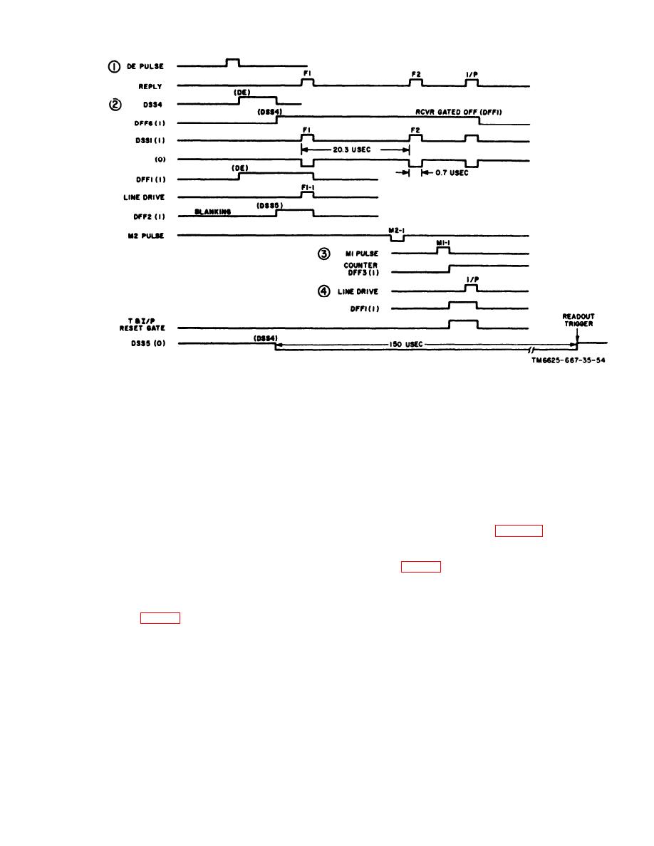
Figure 2-4. Train plus I/P pulse timing diagram. |
|
||
| ||||||||||
|
|
 TM
11-6695-667-45/NAVSHlPS
0969-249-8010/NAVAIR
16-30APM123-2/TO
33A1-3-367-22
Figure 2-4. Train plus I/P pulse timing diagram.
RF pulses are routed by the self-test relay to the
error detector, bypassing preselect or A15Z1. The
detected video is amplified by the video amplifier
as during normal tests. When the test set RF level
is normal, the pulse are gated and shaped by
video shaper DSS1. These pulses are compared
at the error detector with those from the encoder.
An accept indication is provided when all appli-
cable circuits are performing correctly. Receiver
gate 2 is disabled when encode enable IFF1 is re-
set by the DE (P3) pulse (para 2-2d).
2-8. Frequency-Power Test
A frequency-power test can be performed to deter-
mine whether the transponder transmitter or its
2-7. Self-Test Operation
associated coder is causing a reject. When this test
is performed, errors caused pulse information are
inhibited at the error detector. At least one pulse
During self-test, the encoder, modulator and trans-
must be received to determine the transponder
mitter, receiver section, and reply evaluator are
transmitter frequency and power level. If a pulse
tested. The receiver gate is enabled by encode en-
is not received, a reject will occur, indicating that
able IFF1 during self-test. The transmitter section
Change 1
2-9
|
|
Privacy Statement - Press Release - Copyright Information. - Contact Us |
