 |
|||
|
|
|||
|
Page Title:
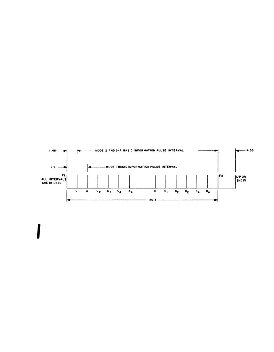
Figure 2-2. Typical SIF type reply trains. |
|
||
| ||||||||||
|
|
 TM 11-6625-667-45/NAVSHIPS 0969-249-8010/NAVAIR 16-30APM123-2/TO 33A1-3-367-99
f. Readout Control and Reply Evaluator. The
triggers the blanking circuit again. Since the
readout control is performed by readout DFF5. It
blanking circuit was reset by the action of the first
is initially reset (reject state) by the decode en-
F1 pulse, the second F1 pulse will cause it to go
able pulse produced by the encoder P3 interroga-
in a set state. This state is maintained until an
tion pulse. In this state, its output is low and is
M2 reset pulse appears. The M2 pulse is the F1
coupled to the reply evaluator. When an error is
pulse coupled from the encoder mode 2 P1 delay
line pulse output. This tap is located 20 microsec-
not sensed by the error detector (e above), the
onds down the delay line; therefore, blanking
reset period is maintained for 150 microseconds.
periods will begin after the second, third, and
After this period, the error blanking circuit and
fourth reply F1 pulse and terminate before their
read delay DSS5 gate on the readout gate. This
respective F2 reply pulse. This blanking period
action in turn triggers DFF5 and causes it to set
permits only F1 and F2 pulses to be detected at
(accept state). If an error is sensed by the error
the error detector during the last three trains of
detector, it sets DFF5 before 150 microseconds.
an emergency reply.
When it is triggered by the readout gate output,
(2) Error detection. The error detector senses
a reject condition is established. The state of DFF5
the presence of pulses and determines whether
is sensed by the reply evaluator. When 80 percent
they are properly positioned. Each reply pulse,
or more correct replies cause a set state to occur
after the F1 pulse, is compared against its corre-
after 150 microseconds, the reply evaluator pro-
sponding pulse of the comparison pulse train. If
vides an accept readout. When 50 percent or less
a pulse is missing or not properly positioned, an
of these replies cause this set state after 150 micro-
error set pulse is applied to readout DFF5 (f
seconds, a reject readout is provided.
below.
Figure 2-2. Typical SIF type reply trains.
2-6
Deleted.
Change
1
2-7
|
|
Privacy Statement - Press Release - Copyright Information. - Contact Us |
