 |
|||
|
|
|||
|
Page Title:
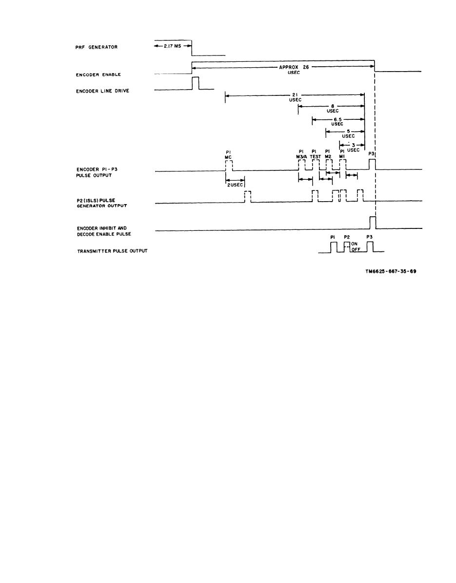
Figure 2-1. Encoder timing diaqram. |
|
||
| ||||||||||
|
|
 TM 11-6625-667-45/NAVAR 16-30APM123-2/T0 33A1-3-367-22
Figure 2-1. Encoder timing diaqram.
directional horizontal field pattern of the antenna
used to obtain these conditios. Encoder P2 pulses
are directed to the adjustable low P2 pulse modu-
helps reduce interference to and from other RF
later driver when the ISLS switch is OFF. When
systems. It is mounted in a horizontal plane on the
control panel of the test set to radiate a vertically
the ISLS switch is ON, the P2 pulse is directed
to the main modulator driver along with the P1
polarized signal. Adjustments can be made in this
plane for line-of-sight antenna alignment. Also,
and P3 pulses The transmitted RF output level
it can be adjusted for horizontal polarization. An-
is attenuated approximately 57 db by the 50-foot
tenna bandwidth is sufficient for the transmission
radiation test distance, the RF cable and attenu-
of 1,030-mc and reception of 1,090-mc signals
ator, or the RF cable, attenuator, and antenna test
Received signals travel from the antenna through
hood during umbilical tests. When preadjusted to
the PROBE jack and the normally closed con-
the RF level of 6 dbm, transponder sets with
tacts of self-test relay A15K1 to the receiver
minimum sensitivity limits of 66 dbm may be
section.
checked. Transponder sets that have minimum
b. Antenna Test Hood. When the test hood is
sensitivity limits between --53 and --72 dbm may
used with aircraft Antenna AT-884/APX-44, the
be checked by preadjusting the transmitter power
level between +4 and 15 dbm as required. The
test set L-band antenna is disconnected from the
antenna test hood and antenna perform as follows:
PROBE jack, then the test hood is connected to
this jack through the attenuator and RF cable.
The test hood insures that maximum RF energy is
compact traveling-wave type, is used for trans-
coupled between the test set and the aircraft
mission of the interrogation signal and reception
of the signal during radiation tests. The highly
Change 3
2-3
|
|
Privacy Statement - Press Release - Copyright Information. - Contact Us |
