 |
|||
|
|
|||
|
|
|||
| ||||||||||
|
|
 TM 11-6625-3017-14
SECTION 6
CIRCUIT DIAGRAM
CIRCUIT NOTES
1
ARRANGEMENT
The inter-unit wiring diagram, FO 6-1,
shows all sub-assembly units in
the equipment together with their
reference designators (A1, A2 etc. )
and type numbers (prefixed TM).
Components that are not on a sub-
assembly are part of the main
chassis assembly (designated AO).
Circuit diagrams are arranged
in order of the subassembly
designations.
2.
COMPONENT VALUES
Resistors : No suffix = ohms, k = kilohms, M = megohms.
Capacitors : No suffix = microfarads, p = picofarads.
Inductors : No suffix = henries, m = millihenries, 1 = microhenries.
t : value selected during test, nominal value shown.
3.
VOLTAGES
Printed in italics. Voltages are d. c. and
relative to chassis unless otherwise indicated.
Measured with a 20 k2/V meter.
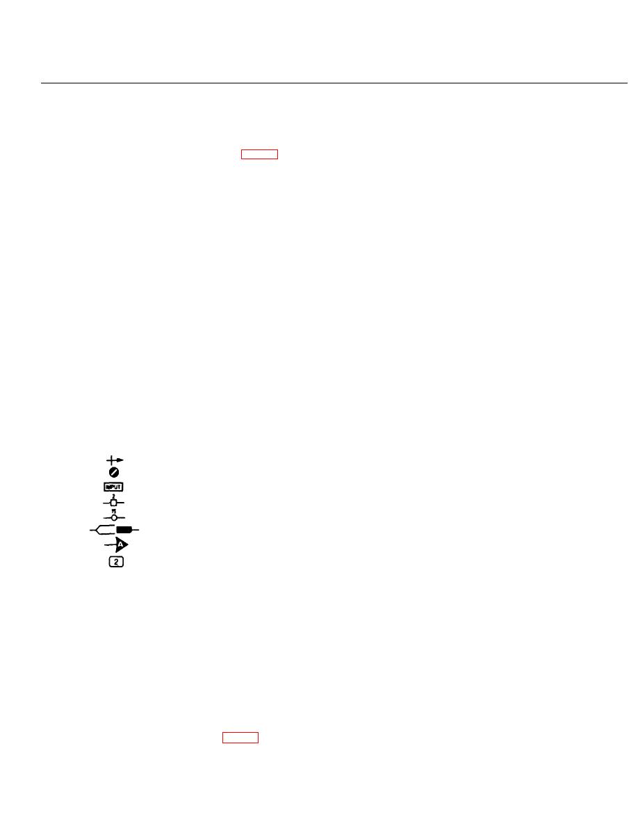
4.
SYMBOLS
arrow indicates clockwise rotation of knob.
preset component.
panel marking.
printed board tag number.
other tag.
printed board edge connector.
indicates points at same supply potential.
waveform reference number.
5.
SWITCHES
Rotary switches are drawn schematically.
Numbers or letters indicate control knob setting
as shown in the key diagrams. Sequence of
sections reading from control knob end is as
follows :-
1F = 1st section, front
1B = 1st section, back
2F = 2nd section, front
etc.
NOTE
6-1/(6-2 blank)
|
|
Privacy Statement - Press Release - Copyright Information. - Contact Us |
