 |
|||
|
|
|||
|
Page Title:
Basic Theory of Mutual Conductance Test |
|
||
| ||||||||||
|
|
 circuit gives an indication of the overall merit
of amplifier tubes under simulated operating
conditions, by measuring the mutual conduct-
ance (G m) of the tube under test. When push-
button 3 -- MUT. COND. is depressed, the
mutual conductance of the tube is indicated on
meter M101 in terms of arbitrary units from
0 to 120. To convert the numerical value of the
meter reading to mutual conductance in mi-
cromhos, refer to paragraph 20, TM 11-6625-
274-12.
f. Gas Test Circuit. This circuit is used to
at the rate of conduction of the tube because of
check for the presence of excessive amounts of
the inertia of the meter movement.
gas in vacuum-type tubes. Excessive gas is in-
b. If the amplifier tube to be tested is sub-
dicated by a change in the position of the meter
stituted for the fixed load resistance and a
pointer due to the shift in the operating points
fixed bias voltage E is applied to the tube (fig.
of the tubes because of gas current in the grid-
5), the meter will still indicate zero because
to-cathode circuit. The gas test is performed by
the amplifier tube, under steady-state condi-
depressing first pushbutton 4 -- GAS 1, then
tions, acts like a fixed resistance.
pushbutton 5 -- GAS 2.
c. If, in addition to the bias voltage, an ac
potential is applied between the control grid
and the cathode of the tube under test, the cir-
To better understand the function and opera-
cuit becomes equivalent to the one used for
ion of the mutual conductance test circuit used
mutual conductance tests in the TV-7(*)/U.
in this test set, a brief review of the basic
When the ac potential causes the bias voltage
principles used follows.
between the control grid and the cathode to be-
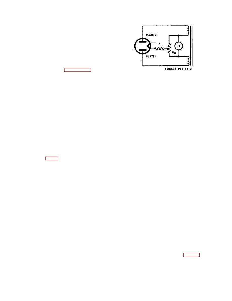
a. The two secondary windings of the trans-
come less negative, plate current through the
former (fig. 4), which are energized from a
tube will increase. Since the plate-cathode re-
60-cycle power source, supply plate voltage to
sistance has decreased, more current will flow
the full-wave rectifier tube. The inner end of
t h r o u g h resistor R M , and the deflecting force
each secondary winding connects to one side of
on the pointer of the meter will be greater than
a dc milliammeter (IG). A center-tapped re-
before the ac potential was applied. When the
sistor, RM, is shunted across the milliammeter.
ac potential causes the bias voltage between the
The load, resistance RL, is connected between
control grid and the cathode to become more
the center tap of the transformer (momen-
negative on the other half cycle, the resistance
tarily neglecting resistor RM) and the cathode
of the tube under test will increase, plate cur-
of the rectifier, as in common full-wave recti-
rent will decrease, and the deflecting force on
fier circuits. When plate 2 is positive with re-
the meter pointer will be less. With unbalanced
spect to the cathode, electrons flow through the
current flow through the meter on adjacent half
upper half of resistor RM and through RL, to
cycles and consequent unequal forces applied to
the cathode, causing the meter pointer to de-
the pointer of the meter, the deflection of the
flect in one direction. When plate 1 is positive
pointer will be proportional to the difference
with respect to the cathode, electrons flow
between the currents. Since the difference be-
t h r o u g h the lower half of resistor R M a n d
tween the currents was created by the ac poten-
through RL to the cathode, causing the meter
tial applied between the control grid and the
pointer to deflect in the opposite directior With
cathode, the meter pointer will indicate the
the load resistance fixed and with equal forces
plate current changes produced by the applied
acting upon the meter each time the tube con-
grid voltage change. The meter, therefore, will
ducts, the meter pointer will indicate zero. The
indicate the mutual conductance (para 10a) of
pointer cannot follow to
oprent variations
the tube under test.
|
|
Privacy Statement - Press Release - Copyright Information. - Contact Us |
