 |
|||
|
|
|||
|
Page Title:
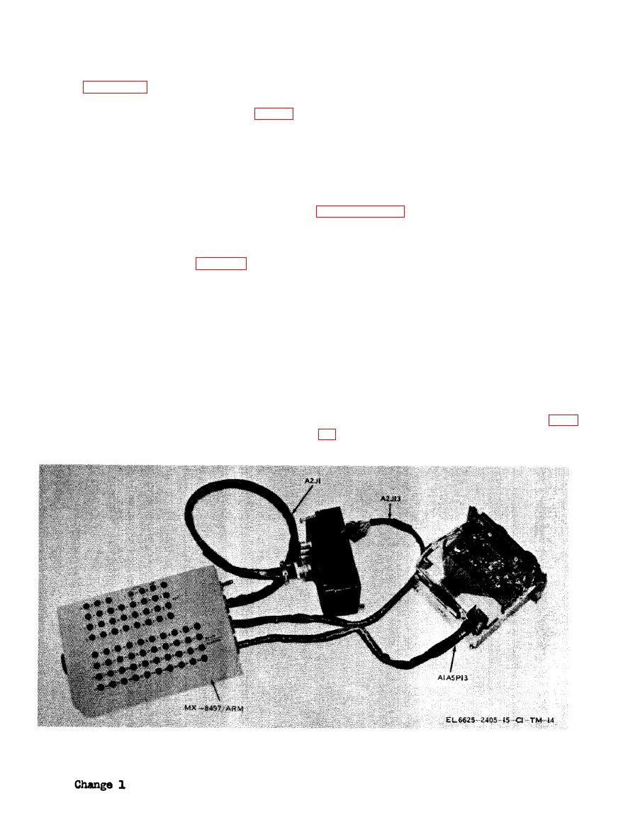
Figure 2-1. Breakout box connected to AN/ARC-114 sections. |
|
||
| ||||||||||
|
|
 TM 11-6625-2405-15
the toggle switch is set to OFF.
c. Connect the breakout box or extender cable
g. Connect the test facilities kit to the power
between the front and rear radio set halves as
source.
shown in figures 2-1, 2-2, and 2-3 for Radio Sets
AN/ARC-114, AN/ARC-115, and AN/ARC-
116, respectively, with breakout boxes, or in fig-
2-6. Test Procedures
ures 2-4, 2-5, and 2-6 for the same radio sets
The DS ,GS, and Depot Maintenance manuals for
with extender cables.
Radio Sets AN/ARC-114, AN/ARC-115, and
d. Connect a power and control cable from
AN/ARC-116 give specific instructions for all
RADIO SET No. 1 jack J1 on the test facilities
procedures required during testing. In respect to
kit to J1 of the breakout box, if used, or to the
the maintenance accessory kit, most instructions
rear of the radio set if an extender cable is used.
involve the making of connections as described in
Cable CX-10889/U is used in Radio Set AN/
ARC-114 tests and CX-10891/U is used in tests
UG-1893/U, UG-J1894/U, and UG-1895/U
of Radio Sets AN/ARC-115 or AN/ARC-116.
adapters.
These cables are part of the MK-994/AR.
a. For all dynamic tests, or for any voltage
checks, applicable controls on Test Facilities Kit
MK-994/AR must be set to on, the toggle switch
quired, plug its jack into the U-92A/U connec-
on the breakout box must be set to ON, and the
tor of the CX-10888/U cable from the HEAD-
function selector switch on the radio set placed in
SETS 1 connector on the MK994/AR. Cables
any position except OFF. For resistance checks,
CX-12175/ARM and CX-12176/ARM are sup-
either disconnect power to the MK-994/AR or
plied to connect the termination box to audio in-
set the toggle switch on the breackout box to OFF.
put or audio output test equipments (MIC or
HDST double banana plug jacks respectively).
This permits measurements on the input lines
The audio circuits are connected through the ter-
(jacks on breakout boxes labeled A2J1 ), on ex-
tender cards (b below), various accessible points
mination box, cable CX-10888/U, the MK-994/
AR, and cable CX-10889/U or CX-10891/U (d
on the radio set exposed front and rear sections,
above) to the breakout box or directly to the rear
and at the front-rear section connectors (at the
lower set of jacks on the breakout boxes (figs.
of the radio set.
f. If a breakout box is used, check to see that
|
|
Privacy Statement - Press Release - Copyright Information. - Contact Us |
