 |
|||
|
|
|||
|
Page Title:
RADIO FREQUENCY ASSEMBLY (A1A1) ALIGNMENT |
|
||
| ||||||||||
|
|
 T. O. 12P4-2APX-192
NAVAIR 16-35TS1843-1
TM 11-6625-1646-25
g. Place transponder test settest setAN/APM-362
9-19. RADIO FREQUENCY ASSEMBLY (A1A1) ALIGNMENT.
controls in the following positions:
9-20.
Radio frequency assembly alignment must be
OPERATE/STANDBY - STANDBY
performed following repair or replacement of subassemblies
TS1843( )/APX POWER AND CONTROL - OFF
AlAlA2 through AlAlA5.
Following alignment perform a
3. Perform reply power alignment as follows:
complete checkout per paragraph 9-13. Proceed as follows:
a. Place transponder test settestsetAN/APM-362
1. Turn on test equipment and allow adequate warm-up time
controls in the following positions:
per manufacturer's instructions.
OPERATE/STANDBY- STANDBY
2. Perform reply frequency alignment as follows:
TS1843( )/APX POWER AND CONTROL -OFF
a. Place transponder test set test setAN/APM-362
REPLY FREQUENCY SELECT MHZ - 1090
controls in the following positions:
NOTE
OPERATE/STANDBY - STANDBY
Prior to installation of electronic test
TS1843( )/APX POWER AND CONTROL -OFF
extender cards a hole must be drilled
MODE SELECT - MONITOR
through the electronic test extender cards to
PRF SELECT - 400
permit access to A1A1 PWR ADJ
BRACKET SPACING SELECT USEC - 20.30
adjustment screw.
REPLY FREQUENCY SELECT MHZ - 1090
b. If necessary, drill holes in electronic test extender
b. Move TS-1843A/APX RF IN DBW control to 20.
cards to gain access to A1A1 PWR ADJ adjustment screw.
Remove power supply and reply evaluator assembly (A3) and
c. Install electronic test extender card MX-9054/
comparator and decoder assembly (A4) from TS- 1843A/APX.
APM-362 in place of A3 module and MX-9055/APM362 in
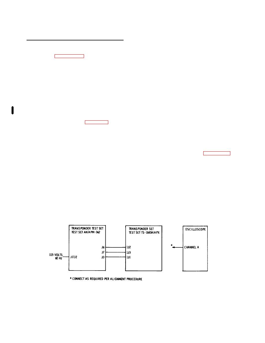
c. Make test connections per figure 9-10. Connect
place of A4. Install A3 and A4 modules on the extender
oscilloscope probe to A1A4J7 (mates with A4-P7) and operate
boards.
with internal sync.
d. Place transponder test settestsetAN/APM-362
d. Place transponder test settestsetAN/APM-362
controls in the following positions:
controls in the following positions:
TS1843( )/APX POWER AND CONTROL - ON
TS1843( )/APX POWER AND CONTROL- ON
OPERATE/STANDBY - OPERATE
OPERATE/STANDBY - OPERATE
e.
Make test connections per figure 9-10.
Connect
OUTPUT POWER LEVEL ADJUST - Adjust for
oscilloscope probe to A4TP1. Oscilloscope display shall be
OUTPUT PEAK POWER LEVEL indication of
two pulses with an amplitude of 2 (*0.2) volts. If pulse
28 DBW.
amplitude is not 2 (*0.2) volts loosen AIA1 PWR ADJ
e. Adjust A1A1Z1, A1A1Z2, and A1A1Z3 to obtain an
adjustment screw. Move power coupler assembly (AlAlA2) to
oscilloscope display of two pulses with an amplitude of 3.5
obtain correct pulse amplitude. Tighten A1A1 PWR ADJ
(*0.2) volts. If pulse amplitude is not 3.5 (*0.2) volts, loosen
adjustment screw.
both A1A1 FREQ ADJ screws. Move frequency coupler
f. Place transponder test set testsetAN/APM-362
assembly (AlA1A3) to obtain the correct pulse amplitude.
controls in the following positions:
Tighten both A1A1 FREQ ADJ screws.
TS1843( )/APX POWER AND CONTROL - OFF
f. Move transponder test set test setAN/APM-362
OPERATE/STANDBY - STANDBY
REPLY FREQUENCY SELECT MHZ control to-4then to +4
g. Remove electronic test extender cards (MX9054/APM-362
positions. Pulse amplitude should be approximately the same
and MX-9055/APM-362) from TS1843A/APX. Install A3 and
at the -4 and +4 switch positions. Adjust A1A1z1, A1A1Z2, and
A4 modules into the TS- 1843A/APX.
A1AlZ3 to ensure pulse amplitude is approximately the same.
Pulse amplitudes should be approximately 1.7 (*0.2) volts.
Figure 9-10. Radio Frequency Assembly (A1Al) Alignment Test Connections
Change 1 9-21
|
|
Privacy Statement - Press Release - Copyright Information. - Contact Us |
