 |
|||
|
|
|||
|
Page Title:
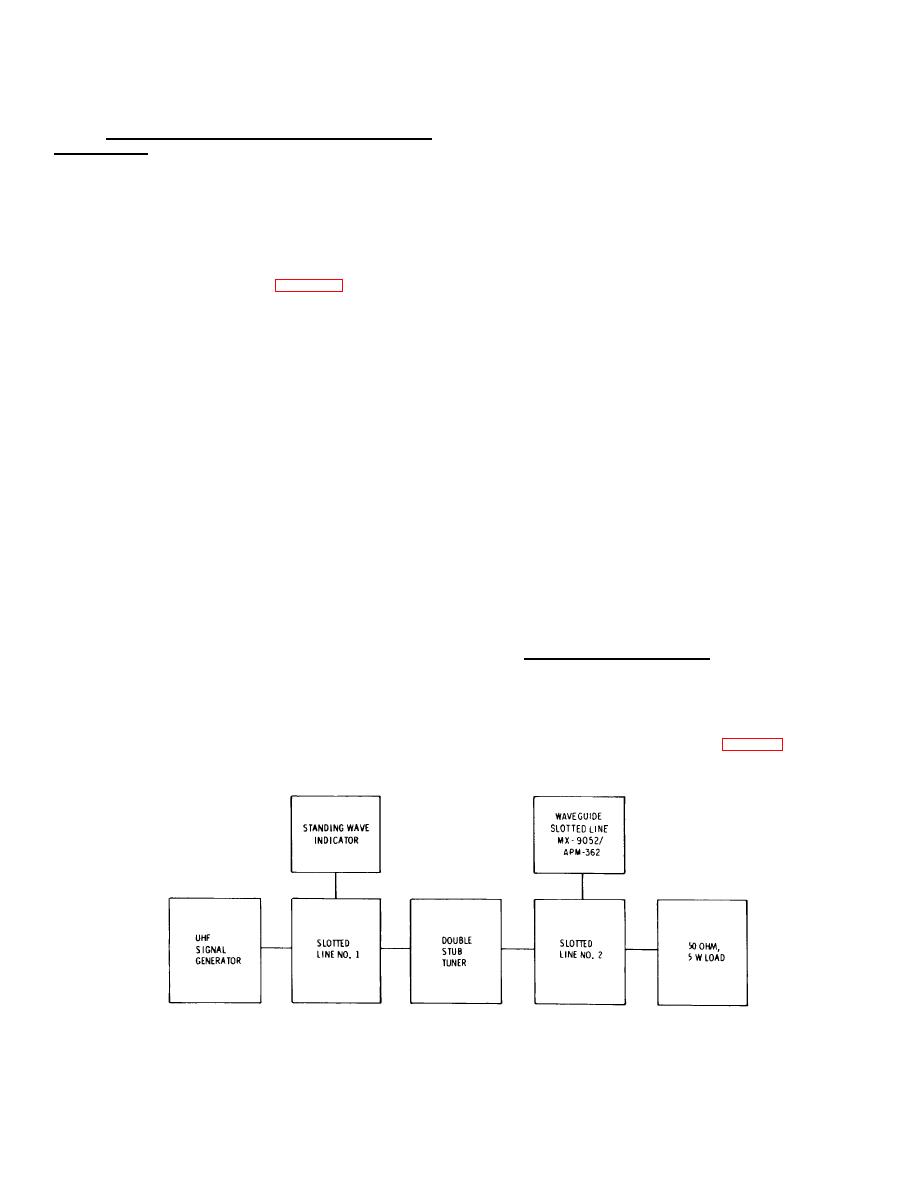
Figure 9-4. Waveguide Slotted Line Adjustment |
|
||
| ||||||||||
|
|
 T.O. 12P4-2APX-192
NAVAIR 16-35TS1843-1
TM 11-6625-1646-25
9. Slide detector probe to obtain minimum standing wave
9-15.
WAVEGUIDE SLOTTED LINE, MX-9052/APM-362
indicator SWR scale deflection.
ADJUSTMENT.
10. Adjust double stub tuner for standing wave indicator meter
9-16. The following procedure is to be used to adjust the
deflection approximately halfway between maximum and
waveguide slotted line used to check TS-1843A/ APX voltage
minimum deflection points.
standing wave ratio detector. Two adjustments are required.
11. Repeat steps 8 through 10 until difference between
One adjustment tunes the double stub tuner to obtain a
maximum and minimum deflection point is 1.03 or less. As
voltage standing wave ratio of 1.03 to 1 over the entire length
final check adjust standing wave indicator GAIN control until
of the slotted line. The second adjustment is to obtain
maximum deflection indication is at 1 on SWR scale. Slide
waveguide slotted line settings that produce mismatches of 7.5
detector probe; minimum deflection point should be 1.03 or
db and 10.5 db. Proceed as follows:
less on standing wave indicator SWR scale. Lock double stub
1. Make adjustment connections per figure 9-4. Do not insert
tuner.
waveguide slotted line at this time.
12. Insert waveguide slotted line into slotted line no. 2.
2. Turn on test equipment and allow adequate warmup time
13. Slide waveguide slotted line for maximum deflection on
per manufacturer's instructions.
standing wave indicator DB scale. Adjust standing wave
indicator GAIN control to obtain 0 on DB scale.
and internal modulation frequency of 1 KHz. Apply power to
14. Slide waveguide slotted line for minimum deflection on
signal generator; adjust modulation to 70% to 80%.
standing wave indicator DB scale. Adjust waveguide slotted
4. Place standing wave indicator controls in the following
line vernier to obtain approximately 7.5 DB indication on
positions:
standing wave indicator.
INPUT SELECTOR - 200 K
15. Repeat steps 13 and 14 until standing wave indicator
RANGE - 50
meter indications are 0 and 7.5 on DB scale as waveguide
METER SCALE - NORMAL
slotted line is moved along slotted line. Record waveguide
GAIN -
Adjust for approximate center scale meter
slotted line vernier setting as the setting that produces a 7.5
deflection.
db mismatch.
5. Move detector probe on slotted line no. 2 to right end of
16. Repeat steps 13 through 15 to obtain waveguide slotted
slotted line.
line vernier setting that produces a 10.5 db mismatch and
6. Adjust slotted line no. 1 detector probe to obtain the
record. Change RANGE scale to 60 to confirm 10.5 db
greater of two standing wave ratio deflections on standing
mismatch.
wave SWR scale.
17. Remove power from signal generator and standing wave
indicator.
Disconnect signal generator, standing wave
NOTE
indicator and slotted line no. 1 from double stub tuner.
Waveguide slotted line adjustment is complete.
The detector probe on waveguide slotted
line must be moved over 180 electrical
9-17. TS-1843A/APX ADJUSTMENT.
degrees as indicated on slotted line to obtain
maximum and minimum indications.
9-18.
Following replacement of the comparator-decoder
assembly (A4) or repair of the ringing oscillator circuit,
7. Slide detector probe to obtain maximum standing wave
adjustment of A4C6 must be accomplished. During A4C6
indication SWR scale deflection.
adjustment, the comparator-decoder assembly must be
8. Adjust standing wave indicator GAIN control to place meter
inserted into the TS-1843A/ APX and the side covers must be
indicator at convenient reference point on SWR scale. Note
in place. Perform A4C6 adjustment per table 9-3.
reference point.
Figure 9-4. Waveguide Slotted Line Adjustment
9-4
|
|
Privacy Statement - Press Release - Copyright Information. - Contact Us |
