 |
|||
|
|
|||
|
Page Title:
LOCATION AND DESCRIPTION OF MAJOR COMPONENTS |
|
||
| ||||||||||
|
|
 TM 11-5920-252-24
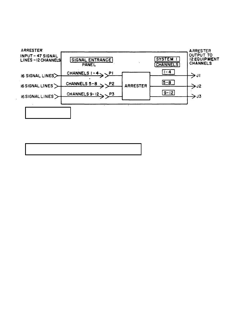
There are 4 signal lines used in each channel. Each arrester input connector (P1, P2 and P3) has 16 pins for 16 signal
lines so 4 channels are used in each connector. Each arrester has 3 input (and output) connectors, so a total of 12
channels, requiring 48 signal lines are provided by the arrester. Use of the arresters is normally deter-
1-7.
CHARACTERISTICS
There are no operating requirements for the arrester such as turn-on, settings or adjustments.
A minimum of maintenance is required. The arrester is used in locations where, for access, shelter equipment must be
disassembled.
1-8.
LOCATION AND DESCRIPTION OF MAJOR COMPONENTS
LOCATION
The location of the arrester is determined by the physical layout of the shelter in which it is used. Normally the arrester is
mounted inside a SIGNAL ENTRANCE panel within a communications shelter. The shelter may have a SIGNAL
ENTRANCE panel on the curbside, the roadside or both the curbside and roadside of the shelter. Refer to the shelter
technical manual (TM) for arrester locations.
DESCRIPTION OF MAJOR COMPONENTS
The arrester has been described physically under the capabilities and features (para 1-6). For a detailed description of the
arrester in its shelter- applied use refer to the shelter manual.
1-7
|
|
Privacy Statement - Press Release - Copyright Information. - Contact Us |
