 |
|||
|
|
|||
|
Page Title:
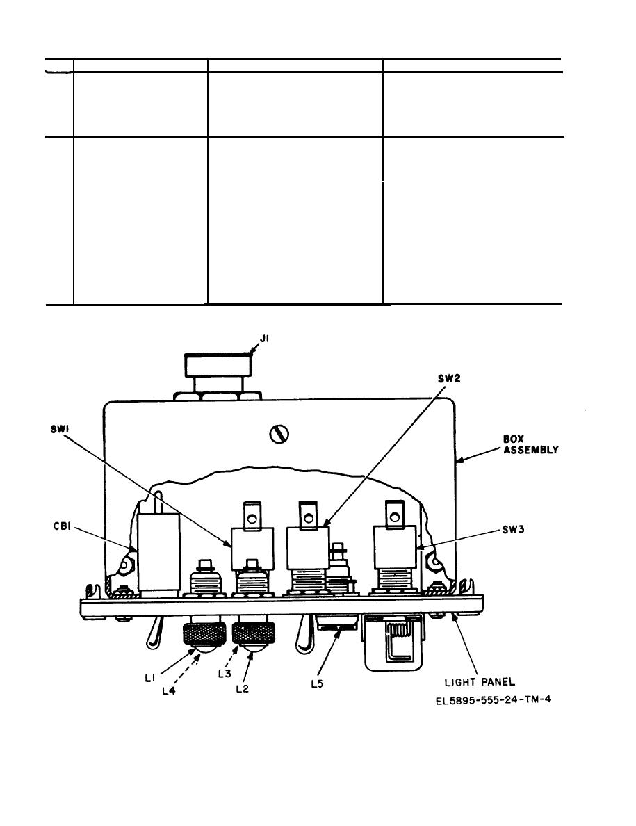
Figure 6-1. Control indicator parts location diagram |
|
||
| ||||||||||
|
|
 TM 11-5895-555-24
Probable Cause
Corrective Action
Malfunction
Item
POWER CIRCUITS
--
NO power input
Switch CB-1 or wiring to pin A of
Check for continuity across CB-1,
6
between CB-1 and pin A of J1.
connector J1.
Check continuity
Wiring from CB-1 to pin B of
7
NO power to TSEC/KY-28
connector J 1.
cipher equipment.
LAMPS and INDICATORS
.
Lamps L4 and L5 or wiring between
8
Panel lamps do not light
Check resistance across L4 and L5
L4 and L5 and pin H of J1.
(should normally be approximately
3 ohms), check continuity between
L4 and L5 and pin H of J1,
Check resistance across L2 (approxi-
Lamp L2 or wiring from pin 1 of
9
Indicator lamp L2 (red)
mately 3 ohms), check continuity
SW-1 to L2.
does not light.
between pin 1 of SW-1 and L2.
Check resistance across L3 (approxi-
Lamp L3, wiring between pin 3 of
10
Indicator lamp L3 (green)
mately 3 ohms), check contin-
SW-1 and L3.
does not light.
uity between pin 3 of SW-1 and
L3.
Check resistance across L1 (approxi-
Lamp L1, wiring between pin 2 of
Indicator lamp L1 (amber)
11
SW-1 and L1.
mately 3 ohms), check continuity
does not light.
between pin 2 of SW-1 and L1.
Figure 6-1. Control indicator parts location diagram.
6-2
|
|
Privacy Statement - Press Release - Copyright Information. - Contact Us |
